
Liquid processing apparatus and liquid processing method

a liquid processing apparatus and liquid processing technology, applied in the direction of chemistry apparatus and processes, cleaning processes using liquids, cleaning processes and apparatus, etc., can solve the problems of large amount of particles contained, large expenses for the purification treatment required for the reuse of recovered chemical liquid, and remaining inside the nozzle hole, so as to achieve the effect of suppressing the generation of water marks on the substrate and efficiently recovering the unused process liquid

Inactive Publication Date: 2008-01-10
TOKYO ELECTRON LTD
View PDF4 Cites 5 Cited by
  • Summary
  • Abstract
  • Description
  • Claims
  • Application Information

AI Technical Summary

Benefits of technology

The present invention provides a liquid processing apparatus and method that can efficiently recover unused process liquid and prevent water mark generation on the substrate. The apparatus includes a holder for holding a substrate, a discharging nozzle for discharging process liquid onto the substrate, a process liquid supply mechanism, and a process liquid sucking mechanism. The method includes the steps of discharging process liquid and a drying gas onto the substrate, and sucking and removing the process liquid remaining inside the discharging nozzle. The process liquid removed by vacuum suction can be reused easily and even if a gas is spurted in the subsequent step, the process liquid is prevented from forming a mist, thereby suppressing water mark generation on the substrate.

Problems solved by technology

In addition, a large amount of particles are contained in the recovered chemical liquid.
It follows that great expenses are needed for the purifying treatment required for the reuse of the recovered chemical liquid.
However, since the nozzle hole is arranged to extend in the vertical direction, the pure water remaining inside the nozzle hole is affected by the gravity and, thus, is unlikely to be discharged completely.

Method used


Image

  • Liquid processing apparatus and liquid processing method
  • Liquid processing apparatus and liquid processing method
  • Liquid processing apparatus and liquid processing method

Examples


Embodiment Construction

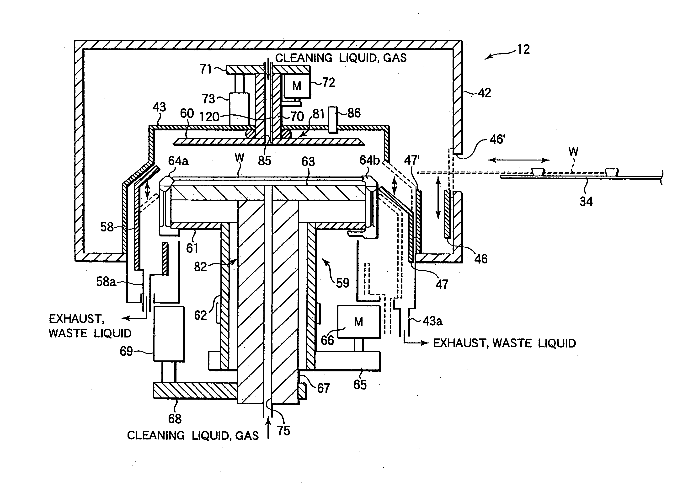
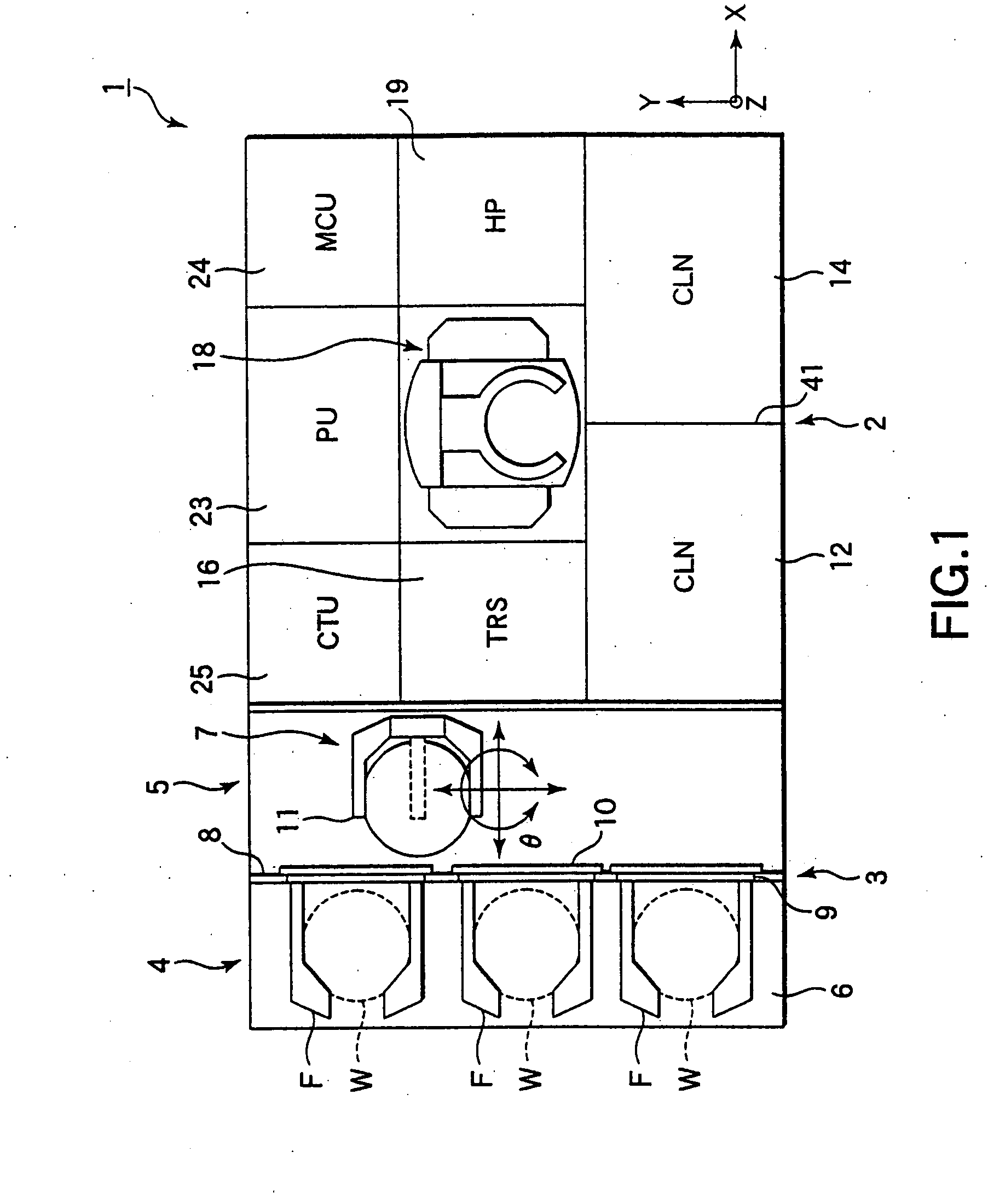
[0031] Some embodiments of the present invention will now be described in detail with reference to the accompanying drawings. The following description covers the case where the technical idea of the present invention is applied to a cleaning process unit, which permits carrying out the cleaning processing on both the front surface and the back surface of a wafer simultaneously, and which is mounted to a cleaning processing system in which the transfer of a wafer into the system, the cleaning / drying processing, and the transfer of the wafer out of the system are carried out consistently.

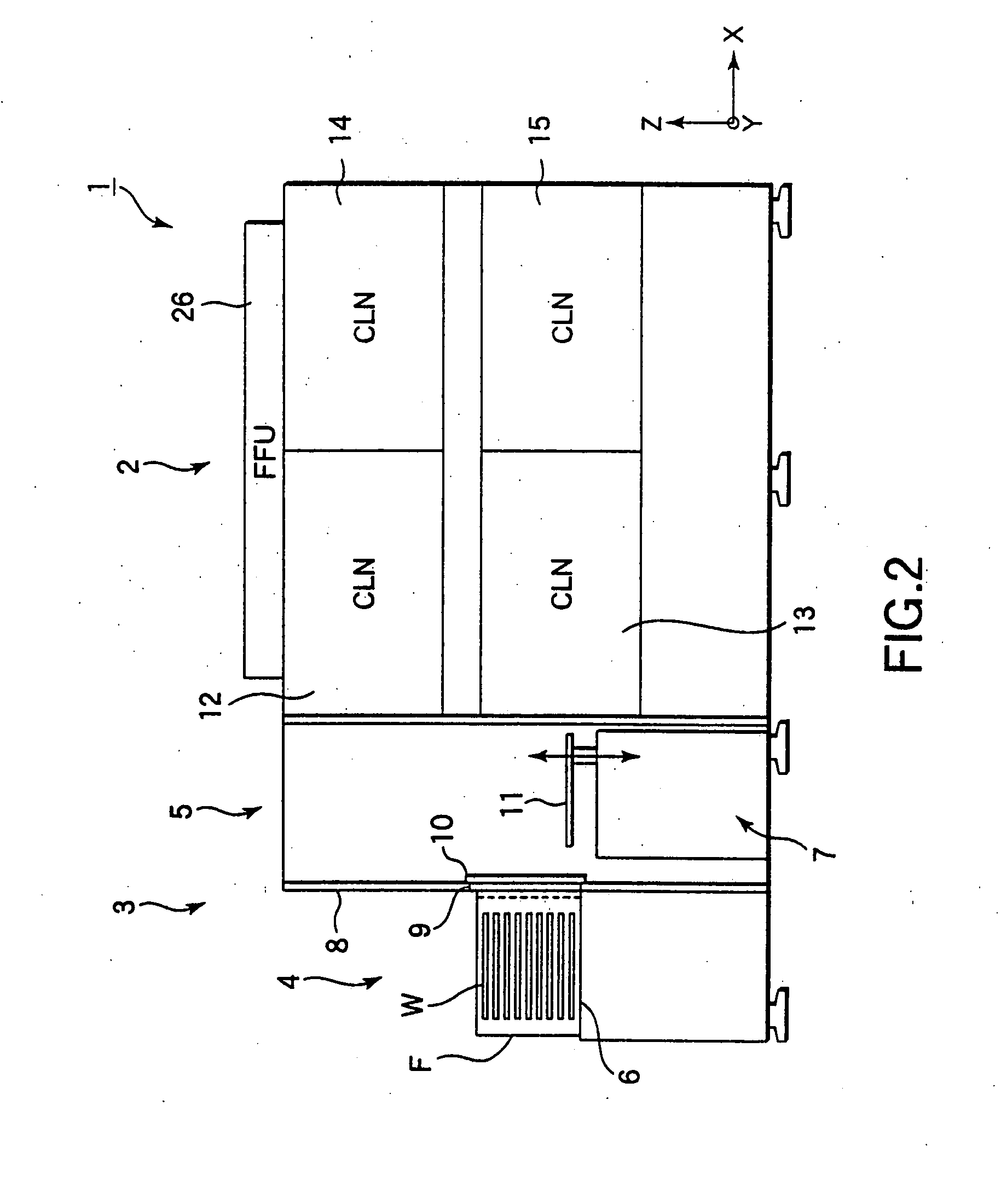
[0032]FIG. 1 is a plan view schematically showing the construction of a cleaning processing system 1, and FIG. 2 is a side view of the cleaning processing system 1 shown in FIG. 1. The cleaning processing system 1 comprises a cleaning processing portion 2 for applying a cleaning processing to the wafer W and a thermal treatment to the wafer W after the cleaning processing, and a loading / unloading po...


PUM

PropertyMeasurementUnit
liquidaaaaaaaaaa
speedaaaaaaaaaa
chemicalaaaaaaaaaa

Abstract

A cleaning processing apparatus comprises a spin chuck for holding a wafer W, an under plate being positioned to face the back surface of the wafer W with a prescribed gap provided therebetween, a support member for supporting the under plate, and a nozzle hole formed to extended through the plate member and the support member. A chemical liquid, a pure water and a gas can be supplied into a nozzle hole through opening-closing valves, and the chemical liquid and the pure water remaining inside the nozzle hole can be sucked by a sucking device. A pure water remaining inside the nozzle hole is sucked and removed by using the sucking device after the processing of the wafer W with a pure water and, then, a gas is spurted onto the back surface of the wafer W.

Description

BACKGROUND OF THE INVENTION [0001] 1. Field of the Invention [0002] The present invention relates to a liquid processing apparatus and a liquid processing method for applying a liquid processing such as a cleaning processing to various substrates such as a semiconductor wafer and an LCD substrate. [0003] 2. Description of the Related Art [0004] In, for example, the manufacturing process of a semiconductor device, used is a wafer cleaning apparatus for cleaning a semiconductor wafer with a chemical liquid or a pure water so as to remove the particles, organic contaminants, and metal impurities attached to the wafer and to remove, for example, polymers after the etching processing. [0005] As a wafer cleaning apparatus, known is a so-called “single wafer type cleaning apparatus”, in which a chemical liquid is supplied onto the front and back surfaces of a wafer, which is held on a spin chuck in substantially a horizontal posture, under the state that the wafer is left stationary or is ...

Claims


Application Information

Patent Timeline
Patent Type & Authority Applications(United States)
IPC IPC(8): B08B5/04C23G1/36H01L21/027H01L21/00H01L21/304
CPCH01L21/67051H01L21/304
Inventor ORII, TAKEHIKOMUKOYAMA, MASAHIRONANBA, HIROMITSU
Owner TOKYO ELECTRON LTD
Learn More