
Multifunctional neck brace

a neck brace and multi-functional technology, applied in medical science, non-surgical orthopedic devices, fractures, etc., to achieve the effects of improving comfort in patents, strengthening cervical muscles, and preventing cervical atrophy

Inactive Publication Date: 2008-01-03
THE JOHN HOPKINS UNIV SCHOOL OF MEDICINE
View PDF21 Cites 16 Cited by
  • Summary
  • Abstract
  • Description
  • Claims
  • Application Information

AI Technical Summary

Benefits of technology

[0011] A novel neck brace for use in the decompression of the cervical region of the spinal column. Such a device will be used by patients that require chronic decompressive therapy (pre- or post-operation), patients in the perioperative period and patients with a condition that does not require surgery but are still in need of decompressive therapy for pain relief. The necessity for a novel device stems from the fact that current methods achieve cervical elongation via braces that are uncomfortable and in some cases overly immobilizing, or via even more obtrusive methods (i.e. inversion therapy and head / neck pulley systems.
[0012] The present invention provides novel neck brace assemblies for therapeutic applications including static decompression, dynamic decompression, strengthening of cervical muscles, prevention of atrophy of cervical muscles, graduating mobility and improved comfort in patents with disease attributable to the cervical region of the spinal column. The devices disclosed and suggested can be used by patients that require acute, intermittent or chronic decompression therapy. Non-operative, pre-operative and post-operative applications are envisioned. Furthermore, short term, intermittent and chronic use is proposed.

Problems solved by technology

The necessity for a novel device stems from the fact that current methods achieve cervical elongation via braces that are uncomfortable and in some cases overly immobilizing, or via even more obtrusive methods (i.e. inversion therapy and head / neck pulley systems.

Method used


Image

  • Multifunctional neck brace
  • Multifunctional neck brace
  • Multifunctional neck brace

Examples


Embodiment Construction

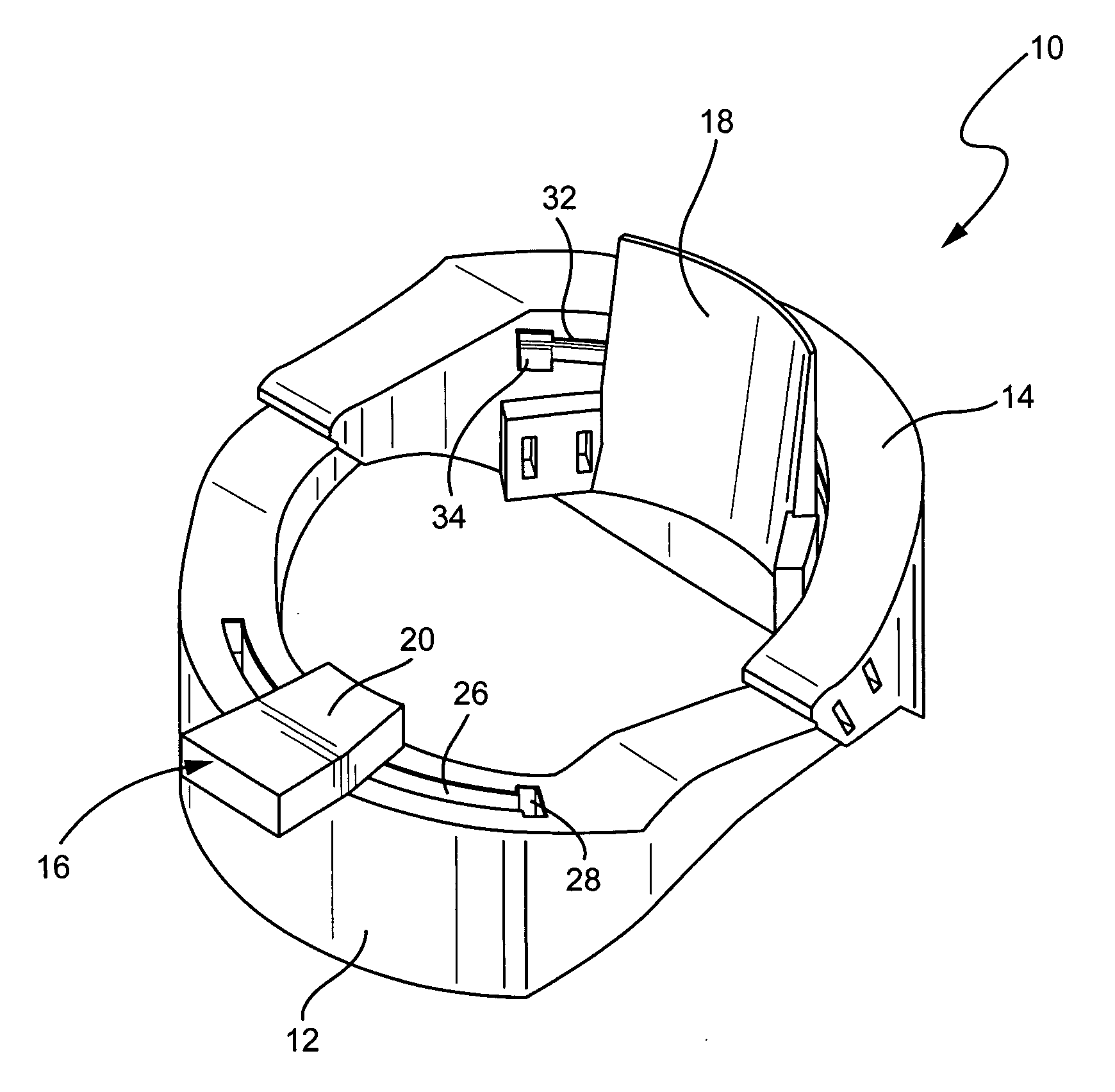
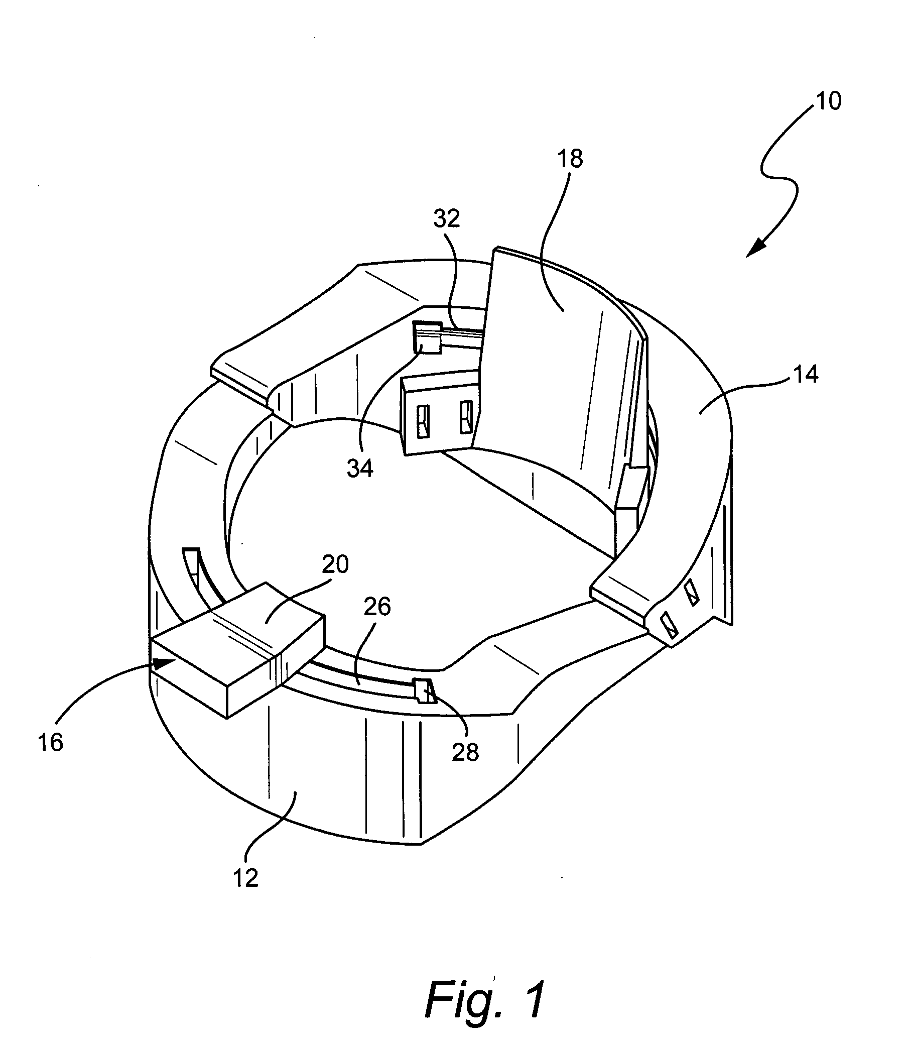
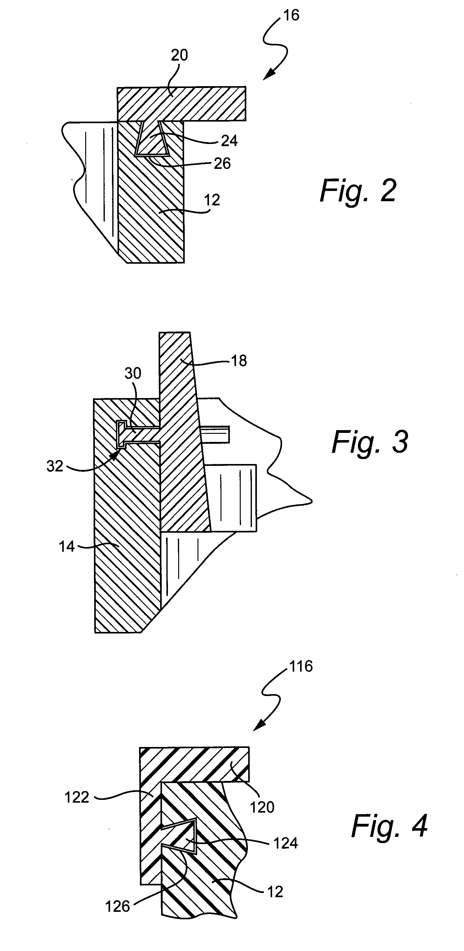
[0021] The quality of life of the patient is always a primary concern. An object of the brace of the invention is to deliver varying mobility of the cervical region, as opposed to the pure immobility provided by conventional braces. A concern is not to immobilize regions or remove mobility that may be beneficial to the condition. Another objective of the brace is to more evenly distribute the weight of the head over the patient's upper body with intention to avoid discomfort from points of concentrated pressure.

[0022] Currently, cervical collars substantially preclude movement of a patient's neck, which is the appropriate function for many cervical injuries. But while some acute cervical injuries require complete immobilization, other patients (such as those without injuries to their C-1 and C-2 vertebrae) prefer and benefit from the ability to rotate their head from side to side. Moreover, in the case of patients recovering from cervical surgery, a collar which can be customized t...


PUM


Abstract

A cervical collar that allows varying mobility to the cervical region with the range of motion or degree of mobility being adjustable and quantifiable. The customizable collar having adjustable and quantifiable mobility allows not only graduated mobility for the patient and consequently progressive strengthening but still protects the injured or diseased cervical segments. The cervical collar may also provide a user-defined and adjustable distraction force that in the medical setting allows physicians or rehabilitating specialists to adjust, graduate and monitor the amount of distraction force being applied to the cervical column. In a home use setting, patients are able to select a comfortable amount of force to counter the weight of the head. In addition to graduated rotation and / or an adjustable distraction force, a minimalist cervical collar configuration is provided that is less obtrusive, less conspicuous, light weight and can be worn in part under clothing.

Description

[0001] This application claims the benefit of U.S. Provisional Application Ser. No. 60 / 798,730, which was filed May 9, 2006, the disclosure of which is incorporated herein by this reference.BACKGROUND OF THE INVENTION [0002] The human spine is divided into the cervical, thoracic, lumbar and sacral vertebrae. Of these, the cervical spine (consisting of the top seven vertebrae closest to the skull) presents the highest risk of injury. This is due to a comparatively smaller amount of muscular support and the fact that they must support and bear the forces resulting from head weight and movement. The first two cervical vertebrae, the atlas (C-1) and axis (C-2) vertebrae, are designed specifically for rotation. [0003] To understand the cause of the various types of conditions affecting the cervical spine, it is first appropriate to take a closer look at the individual bones of the spine: the vertebrae. The vertebrae are stacked one on top of the other, separated by intervertebral discs, ...

Claims


Application Information

Patent Timeline
Patent Type & Authority Applications(United States)
IPC IPC(8): A61F5/055
CPCA61F5/055
Inventor GEHLBACH, PETER LOUISBENSON, BRIAN CHRISTOPHERCORTES, HELENA MARIADAVENPORT, MICHAEL S.HARRISON, RYAN MARQUESHWANG, KARINKAPP, GREGORY MICHAELLEE, CHRISTOPHER YENSENLERMAN, JOSHUA ADAMLI, TUOWONG, JOHNSON C.
Owner THE JOHN HOPKINS UNIV SCHOOL OF MEDICINE
Learn More