Fuel cell
a fuel cell and fuel gas technology, applied in the field of fuel cells, can solve the problems of uneconomically required production, inability to achieve desired power generation performance, and inability to accurately control the flow rate of oxygen-containing gas and fuel gas, and achieve the effect of uniform power generation reaction and simple and economical structur
- Summary
- Abstract
- Description
- Claims
- Application Information
AI Technical Summary
Benefits of technology
Problems solved by technology
Method used
Image

Examples
first embodiment
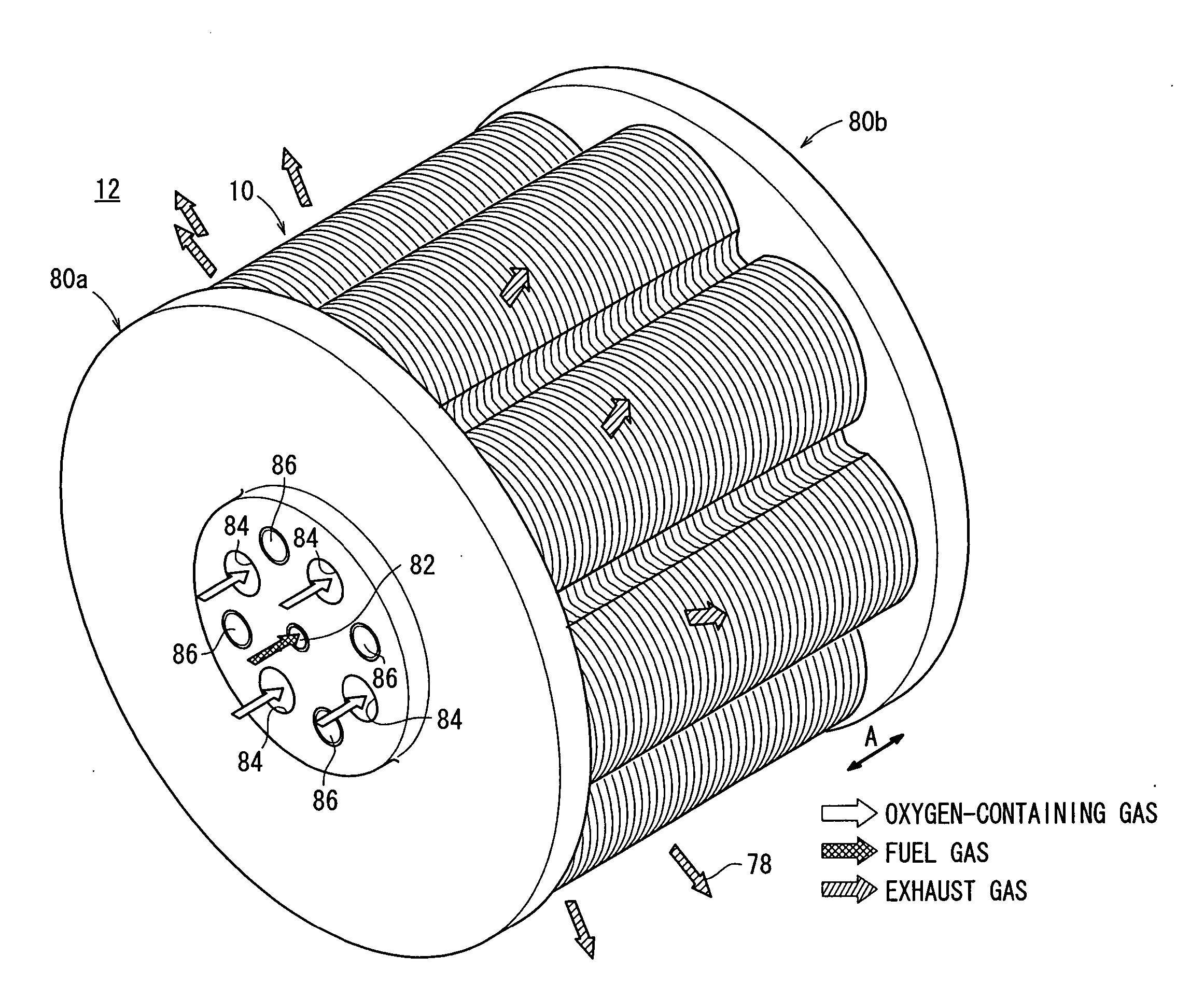
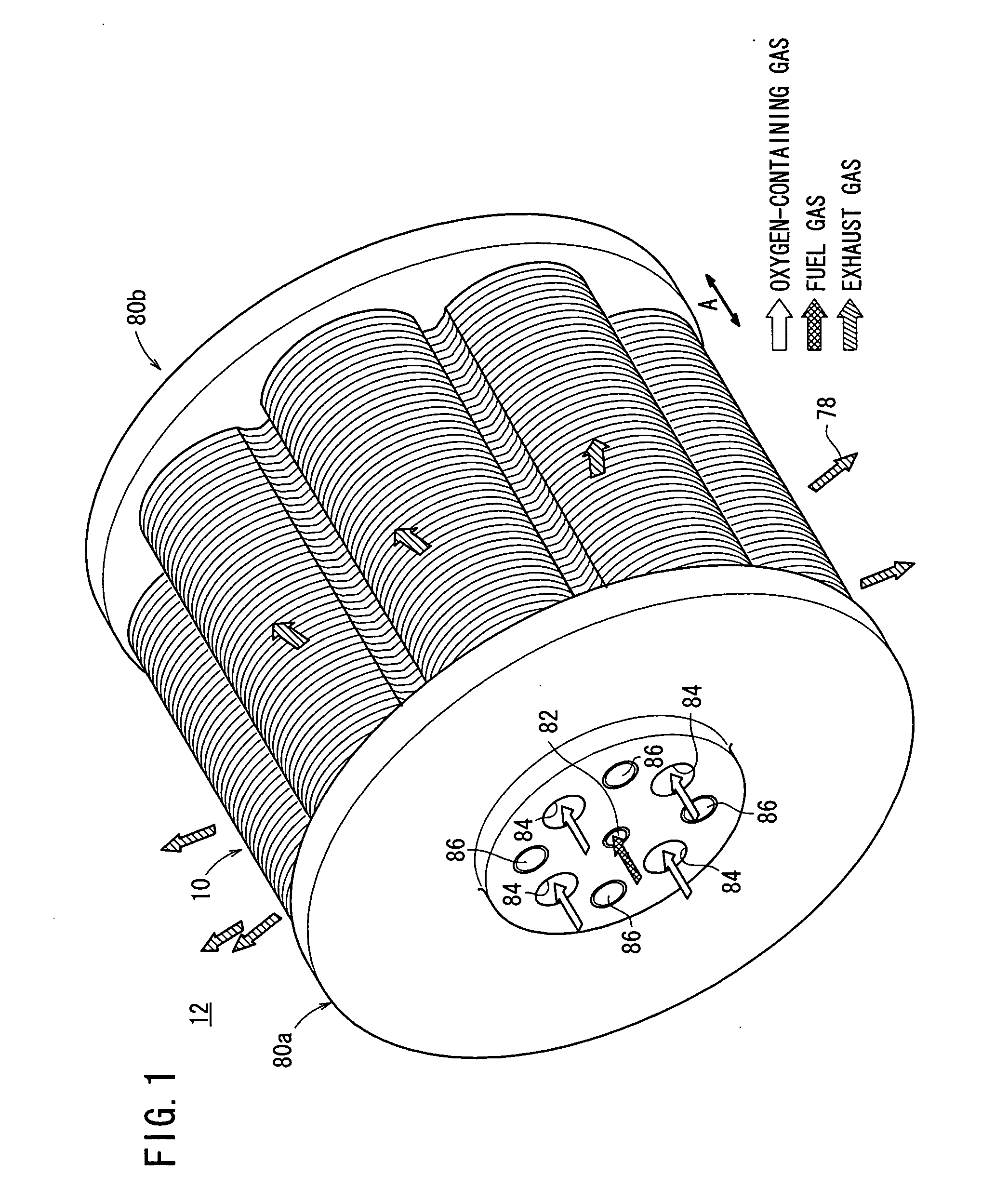
[0047]FIG. 1 is a perspective view schematically showing a fuel cell stack 12 formed by stacking fuel cells 10 according to the present invention in a direction indicated by an arrow A.
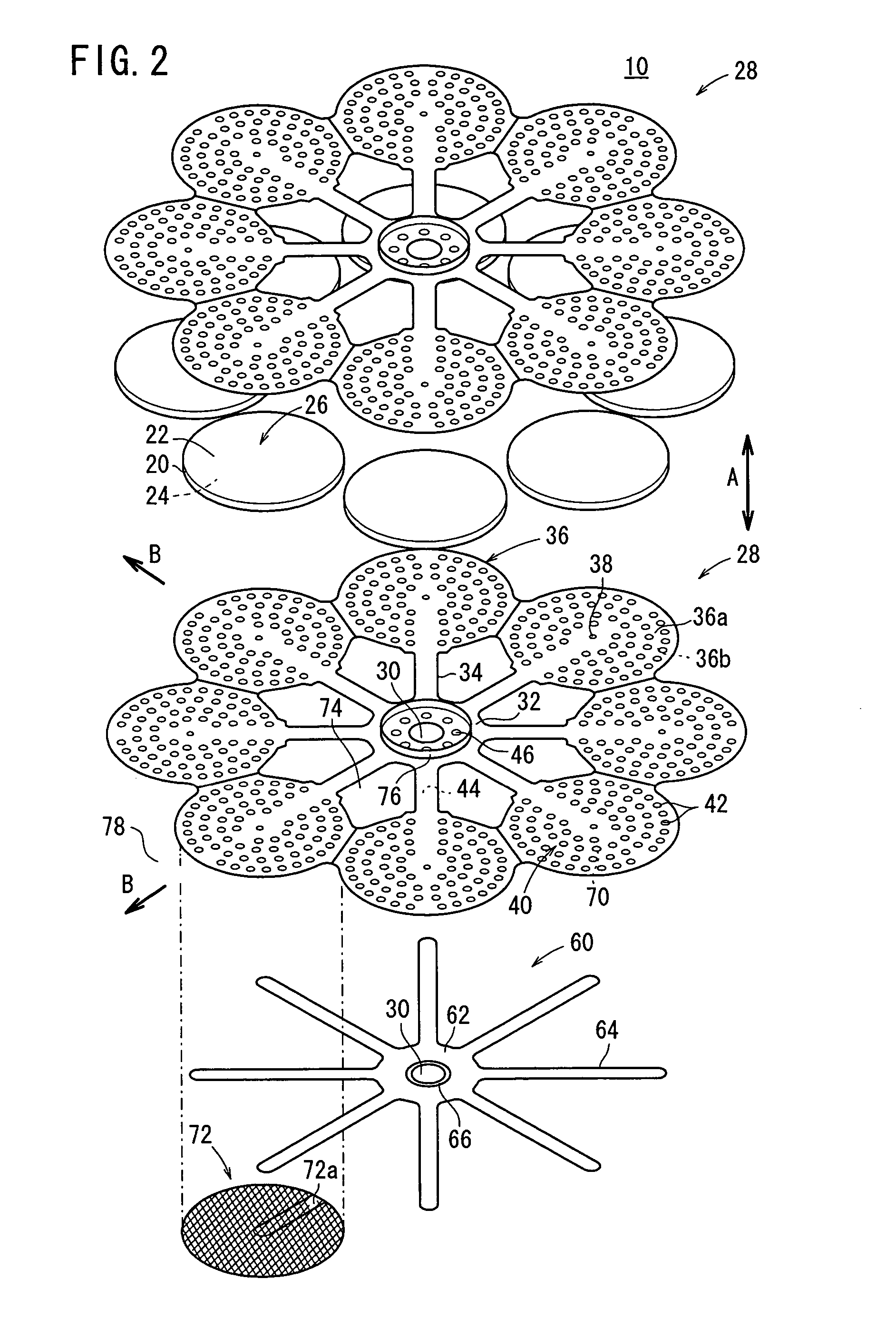
[0048] The fuel cell stack 12 is used in various applications, including stationary and mobile applications. For example, the fuel cell stack 12 is mounted on a vehicle. The fuel cell 10 is a solid oxide fuel cell (SOFC). As shown in FIGS. 2 and 3, the fuel cell 10 includes electrolyte electrode assemblies 26. Each of the electrolyte electrode assemblies 26 includes a cathode 22, an anode 24, and an electrolyte (electrolyte plate) 20 interposed between the cathode 22 and the anode 24. For example, the electrolyte 20 is made of ion-conductive solid oxide such as stabilized zirconia. A barrier layer (not shown) is provided at least at the outer circumferential edge of the electrolyte electrode assembly 26 for preventing the entry / emission of the oxygen-containing gas and the fuel gas.
[0049] A pluralit...
third embodiment
[0085]FIG. 9 is an exploded perspective showing a fuel cell 106 according to the present invention. FIG. 10 is a cross sectional view showing operation of the fuel cell 106.
[0086] The fuel cell 106 includes a separator 107, and a deformable elastic channel member such as an electrically conductive mesh member 72 is provided on a surface 36a of the circular disk 36 of the separator 107. The electrically conductive mesh member 72 forms a fuel gas channel 40 for supplying the fuel gas along a surface of the anode 24, and tightly contacts the anode 24 (see FIGS. 9 and 10).
[0087] In the third embodiment, by deformation of the mesh member 72, the mesh member 72 tightly contacts the anode 24.
fourth embodiment
[0088]FIG. 11 is an exploded perspective view showing a fuel cell 108 according to the present invention. FIG. 12 is a cross sectional view showing operation of the fuel cell 108.
[0089] The fuel cell 108 includes a separator 109, and the channel member 60 is fixed to a surface of the separator 109 facing the anode 24. A plurality of fuel gas inlets 38 are formed at each of the front ends of the second bridges 64 of the channel member 60, and the holes 46 are provided around the fuel gas supply passage 30 in the second small diameter end portion 62 of the channel member 60. No fuel gas inlets are provided in the circular disk 36.
PUM
| Property | Measurement | Unit |
|---|---|---|
| elastic | aaaaa | aaaaa |
| ion-conductive | aaaaa | aaaaa |
| area | aaaaa | aaaaa |
Abstract
Description
Claims
Application Information
 - R&D
- Intellectual Property
- Life Sciences
- Materials
- Tech Scout
- Unparalleled Data Quality
- Higher Quality Content
- 60% Fewer Hallucinations
Browse by: Latest US Patents, China's latest patents, Technical Efficacy Thesaurus, Application Domain, Technology Topic, Popular Technical Reports.
© 2025 PatSnap. All rights reserved.Legal|Privacy policy|Modern Slavery Act Transparency Statement|Sitemap|About US| Contact US: help@patsnap.com