
Cavitating Body Sonar System and Process

Inactive Publication Date: 2008-01-03
GEN DYNAMICS INFORMATION TECH
View PDF7 Cites 12 Cited by
  • Summary
  • Abstract
  • Description
  • Claims
  • Application Information

AI Technical Summary

Benefits of technology

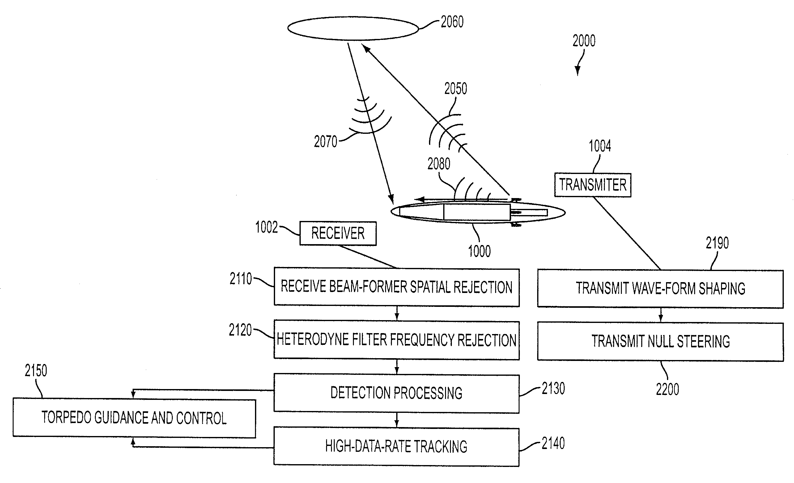
[0014] An exemplary embodiment of the method of the present invention may further include: applying transmit null steering techniques to improve performance of the RWT sonar system for the cavitating body.
[0016] An exemplary embodiment of the method of the present invention may further include: applying receive beam-former spatial rejection to improve performance of the RWT sonar system for the cavitating body.
[0026] An exemplary embodiment of the present invention may capitalize on improved sonar system performance that can be derived from simultaneously transmitting a sonar signal while receiving the echo of that signal from targets or other objects of interest. This technique may allow continuous processing of the received signal, as opposed to alternative conventional systems that transmit sonar signals over short time periods, a technique typically referred to as “pinging.” Because the signal is continuously received and processed, the total amount of acoustical energy available to detect, classify, localize, track, and / or target underwater objects, can be significant, even if the amount of transmitted power is relatively small or the target strength is weak.

Problems solved by technology

However, the small wetted area of the cavitator poses problems if that area is to host transducers serving as forming the elements of a sonar system.
Specifically, the amount of acoustical power that can be transmitted via the small wetted area is limited: overpowering the system causes cavitation on the nominally wetted transducer faces, causing severe performance degradation.
Furthermore, the aperture of the sonar array is limited by the small cavitator diameter, and the number of array elements that can be practically packed within such a small volume is also quite limited, which in turn limits the beam-forming capabilities of the system.
Since drag of such a cavitator is directly proportional to its projected area at the locus of cavity detachment, simply increasing the cavitator size is not a practical option, since it would eliminate the drag advantage that is otherwise gained via supercavitation.
Conventional art thus fails to show how to effectively discriminate between signals that sonar receives from its own transmitter and echoes from the intended target subject to certain linearity and rejection requirements.

Method used


Image

  • Cavitating Body Sonar System and Process
  • Cavitating Body Sonar System and Process
  • Cavitating Body Sonar System and Process

Examples


case b

[0063] In another exemplary embodiment of the invention, further advantages may be achieved including, in an exemplary embodiment, incorporating a transmitter system attached directly to the cavitating body. Another exemplary embodiment, may include a transmitter system located elsewhere in the water. For application to a supercavitating torpedo, such as, e.g., but not limited to, the increased aperture homing cavitator (IAHC) discussed above, according to an exemplary embodiment of the present invention, at least four options may exist, including the following options for locating the transmitter, as depicted in FIG. 7: [0064] Case A—mounted on the platform such as a submarine from which the supercavitating torpedo is launched; [0065] mounted on a device that is separate from the supercavitating torpedo, launched from the same launch platform; [0066] Case C—mounted on the cavitator, and simultaneously serving as the receive array; and, [0067] Case D—mounted elsewhere on the superca...


PUM


Abstract

An exemplary embodiment of the present invention may include a cavitating body sonar system and method. The method may include, in an exemplary embodiment: applying a receiving-while-transmitting sonar signal processing to at least one cavitating body, over an entire range of achievable sonar operating frequencies; applying transmit wave-form shaping to a RWT sonar system employed on the cavitating body; applying heterodyne filter frequency rejection to the RWT sonar system employed on the cavitating body; applying detection processing techniques to the RWT sonar system employed on the cavitating body; employing at least one transducer as an acoustical transmitter near a scattering body comprising the cavitating body, wherein the at least one transducer is strategically located with respect to said cavitating body, at least one target, and a receiver, wherein the receiver lies in a shadow zone of the body, but the at least one target does not; and, employing at least one transducer as an acoustical transmitter near a scattering body comprising the cavitating body, wherein the at least one transducer is strategically located with respect to a cavity, at least one target, and a receiver, wherein direct propagation of a transmitted signal along the outside of the cavity to the receiver is inhibited, and reflected propagation from the acoustical transmitter to the target and thence reflected to the receiver is not inhibited.

Description

[0001] This application is a nonprovisional claiming the benefit under 35 U.S.C. Section 119(e) of U.S. Provisional Patent Application Ser. No. 60 / 809,788, (Attorney Docket No. 41679-231619), filed on 1 Jun. 2006, entitled “Cavitating Body Sonar System and Process,” to Kirschner et al., of common assignee to the claimed invention, the contents of which is incorporated herein by reference in its entirety. [0002] This application is a continuation-in-part of U.S. patent application Ser. No. 10 / 953,300, entitled “Sonar System and Process,” to Lerro, et al., filed on 29 Sep. 2004, which itself claims the benefit under 35 U.S.C. Section 119(e) of U.S. Provisional Patent Application Ser. No. 60 / 506,507, (Attorney Docket No. 41679-202295), entitled “Receive While Transmit (RWT) Sonar,” filed on 29 Sep. 2003, (hereafter “Lerro, et al., (2003)”), of common assignee to the claimed invention, the contents of both of which are incorporated herein by reference in their entirety. [0003] This appl...

Claims


Application Information

Patent Timeline
IPC IPC(8): G01S15/00
CPCG01S15/88G01S15/32
Inventor KIRSCHNER, IVAN N.LERRO, DONALD T.FREEMAN, LARRYMARTINEZ, RUDOLPHUHLMAN, JAMES S. JR.
Owner GEN DYNAMICS INFORMATION TECH
Learn More