
Handover method and base station for a radio communication network

a radio communication network and base station technology, applied in the direction of wireless communication, electrical equipment, selection arrangements, etc., can solve the problem of not being able to evaluate basic information, and achieve the effect of improving the efficiency of handover in radio communication systems

Active Publication Date: 2007-12-27
WSOU INVESTMENTS LLC
View PDF7 Cites 14 Cited by
  • Summary
  • Abstract
  • Description
  • Claims
  • Application Information

AI Technical Summary

Benefits of technology

"The present invention provides a method and a base station for evaluating the radio conditions of a user equipment during handovers in radio communication systems. This evaluation is based on information provided by the source base station to the candidate base station, which can use this information to make informed handover decisions. The invention also allows for the use of distributed RRM, which optimizes the use of radio resources. The technical effects of the invention include improved efficiency of handovers and better detection of uplink signals."

Problems solved by technology

However, in currently known radio communication systems, e. g. the above-mentioned OFDM-based LTE system, there is no possibility to evaluate the basic information listed above since the latter is only locally available.

Method used


Image

  • Handover method and base station for a radio communication network
  • Handover method and base station for a radio communication network
  • Handover method and base station for a radio communication network

Examples


Embodiment Construction

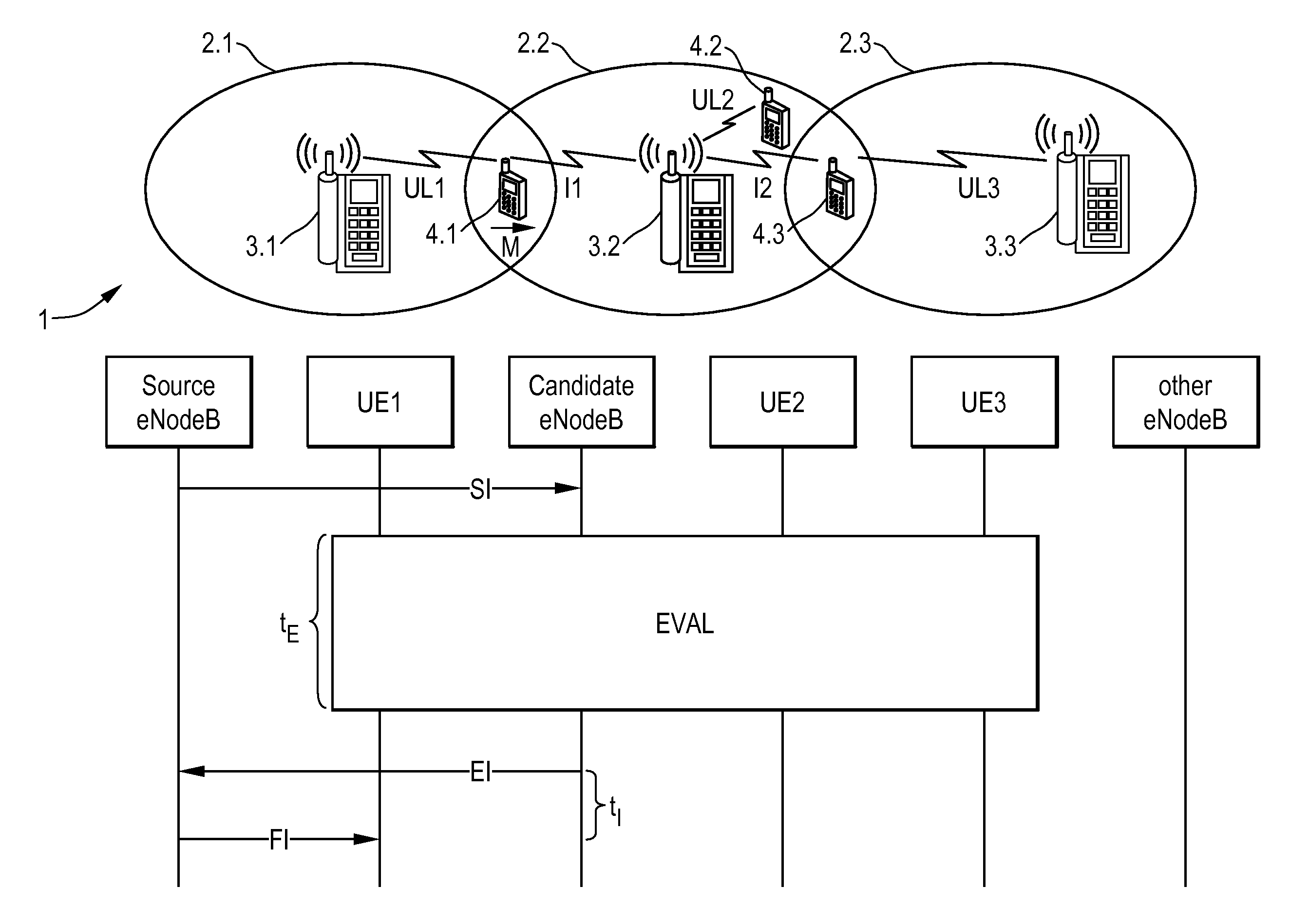
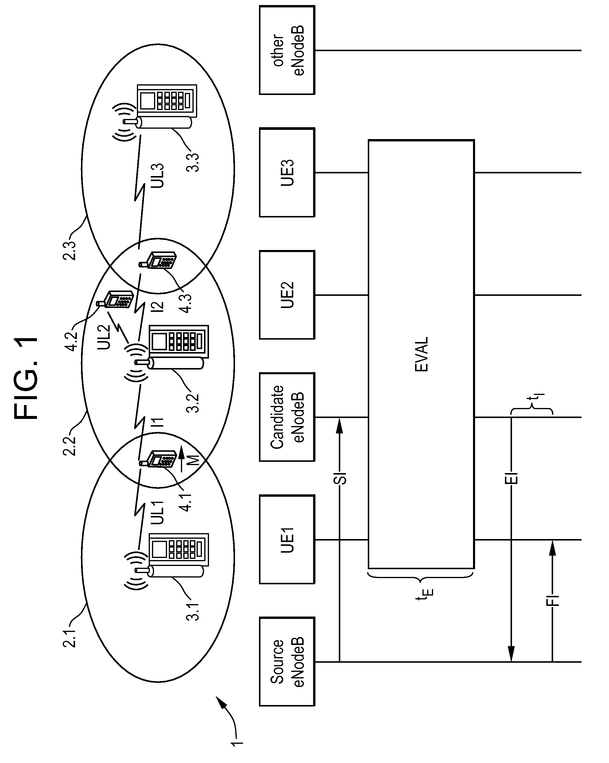
[0047]FIG. 1 shows a combined system architecture and timing diagram for illustrating an embodiment of the method in accordance with the present invention. In the upper part of FIG. 1, there is depicted a mobile communication network 1, e. g. an OFDM (Orthogonal Frequency Division Multiplex) based UMTS-LTE system (Long Term Evolution of Universal Mobile Telecommunications System). Said system or network 1 generally comprises a number of radio cells 2.1, 2.2, 2.3 associated with or served by a respective base station 3.1, 3.2, 3.3. In the context of UMTS, said base stations 3.1-3.3 are also referred to as NodeBs or eNodeBs (evolved NodeBs). For mobile telecommunication purposes, the base stations 3.1-3.3 assign respective radio resources, e. g. in terms of used frequencies, transmit power levels, or the like, to mobile end terminals 4.1, 4.2, 4.3 present inside a respective radio cell 2.1-2.3 associated with that particular base station 3.1-3.3. In the exemplary context considered he...


PUM


Abstract

A method for handover of a User Equipment (UE1) from a source base station (3.1) to a target base station (3.2). The proposed method comprises the steps of:providing User Equipment specific information (SI) from the source base station (3.1) to at least one candidate base station (3.2),evaluating an uplink radio situation during uplink transmission (UL1) of the User Equipment (4.1) to the source base station (3.1) by the at least one candidate base station (3.2),sending information (EI) related to said evaluation to the source base station (3.1) by the at least one candidate base station (3.2), andperforming a handover decision by the source base station (3.1) based on said evaluation.

Description

BACKGROUND OF THE INVENTION [0001]The invention is based on a priority application EP 06 291 040.1 which is hereby incorporated by reference.[0002]The present invention relates to a method for handover of a User Equipment from a source base station to a target base station.[0003]The present invention also relates to a base station for use as a source base station and as a candidate or target base station in a radio communication network comprising a number of User Equipments.[0004]In mobile radio telecommunication systems, in particular systems comprising OFDM (Orthogonal Frequency Division Multiplex) interfaces, such as Long Term Evolution (LTE) of UMTS (Universal Mobile Telecommunications System), a plurality of radio cells is attached to and served by respective base stations. If a mobile end terminal or User Equipment is moving on the periphery of a given radio cell and is about to enter an adjacent radio cell, attachment of said User Equipment can be transferred from a currentl...

Claims


Application Information

Patent Timeline
Patent Type & Authority Applications(United States)
IPC IPC(8): H04Q7/20H04W36/08H04W36/38
CPCH04W36/0055H04W36/0058H04W36/0044H04W36/30H04W36/38H04W72/21
Inventor KAMINSKI, STEPHEN
Owner WSOU INVESTMENTS LLC
Learn More