
Robotic Handling System and Method with Independently Operable Detachable Tools

a robot and handling system technology, applied in the direction of liquid transfer devices, instruments, transportation and packaging, etc., can solve the problems of increasing the risk of sample and/or probe contamination and carryover, increasing the risk of contamination and carryover, and reducing the complexity of coordinating the flow

Inactive Publication Date: 2007-12-27
PARKER HANNIFIN CORP
View PDF99 Cites 61 Cited by
  • Summary
  • Abstract
  • Description
  • Claims
  • Application Information

AI Technical Summary

Benefits of technology

[0012] Accordingly, the invention provides an analytical system and method wherein a plurality of movable devices are used in performing one or more operations at one or more stations. The stations have associated therewith one or more receivers for receiving one or more of the movable devices so that a prescribed operation can be commenced at the respective station. A transport mechanism transports the movable devices from station to station, and a controller directs the transport mechanism to leave at least one of the movable devices with the receiver(s) in a first one of the stations thereby to free the transport mechanism for transport of at least one other movable device between stations while the movable device or devices left at the first station are used to perform a prescribed operation at the first station.
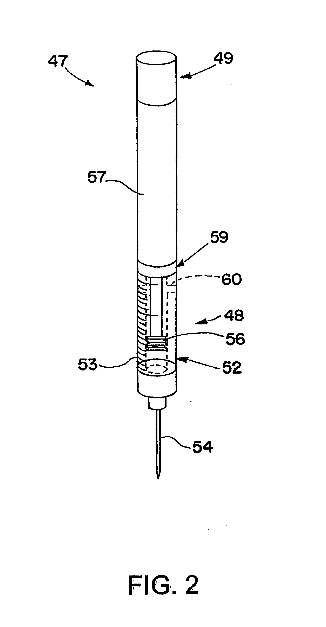
[0016] In other embodiments, the sampling probes may be self-contained thereby eliminating the need for a tether and thus reducing the complexity of coordinating the flow of the sampling probes through the system. An untethered self-contained sampling probe typically would include a plunger and a motive device for moving the plunger in response to a command signal. The command signal may be effected wirelessly between the sampling probe and a stationary system component, and / or by other suitable means.

Problems solved by technology

While such systems are easy to design, build and implement, a disadvantage is that all of the ganged probes must travel in the X, Y and Z axes together.
This increases the risk of sample and / or probe contamination and carryover.
The problem becomes more complex when overall throughput is of concern or when several transportable devices must be administered during execution, especially when individual unit operation time frames are not balanced throughout the workflow.
The prior art systems also are not able to handle failure situations very well.
In a worst case scenario, the system has to shut itself down and wait for repair.

Method used


Image

  • Robotic Handling System and Method with Independently Operable Detachable Tools
  • Robotic Handling System and Method with Independently Operable Detachable Tools
  • Robotic Handling System and Method with Independently Operable Detachable Tools

Examples


Embodiment Construction

[0029] Because the invention was conceived and developed as an adaptive, synchronized motion and fluids system for automating the sample handling process associated with analytical processes and especially bioanalytical processes such as introducing samples into LC systems, HPLC systems, etc., it will be herein described chiefly in this context. However, the principles of the invention in their broader aspects can be adapted to other types of systems, such as automotive production line systems and electronic assembly systems.

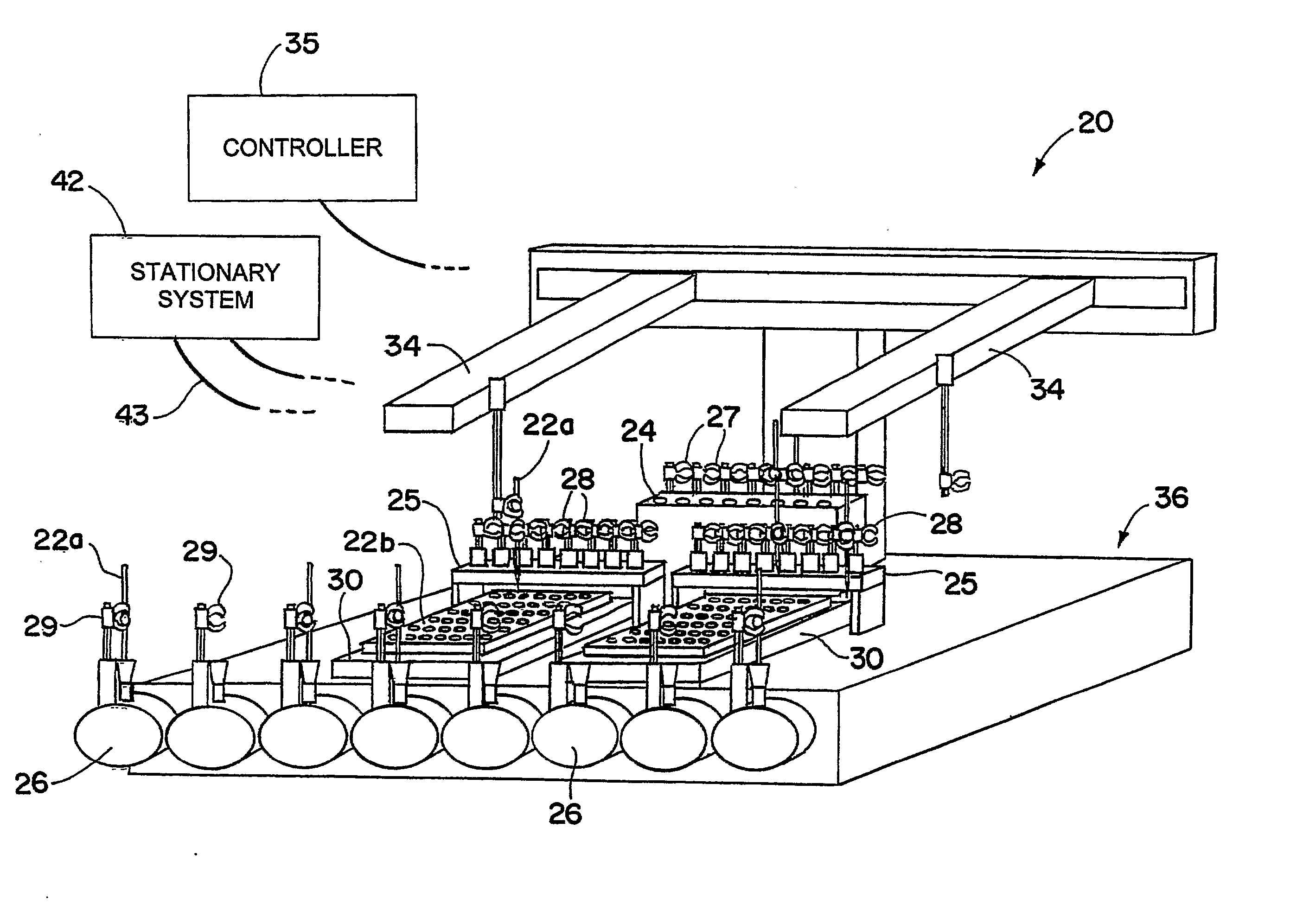
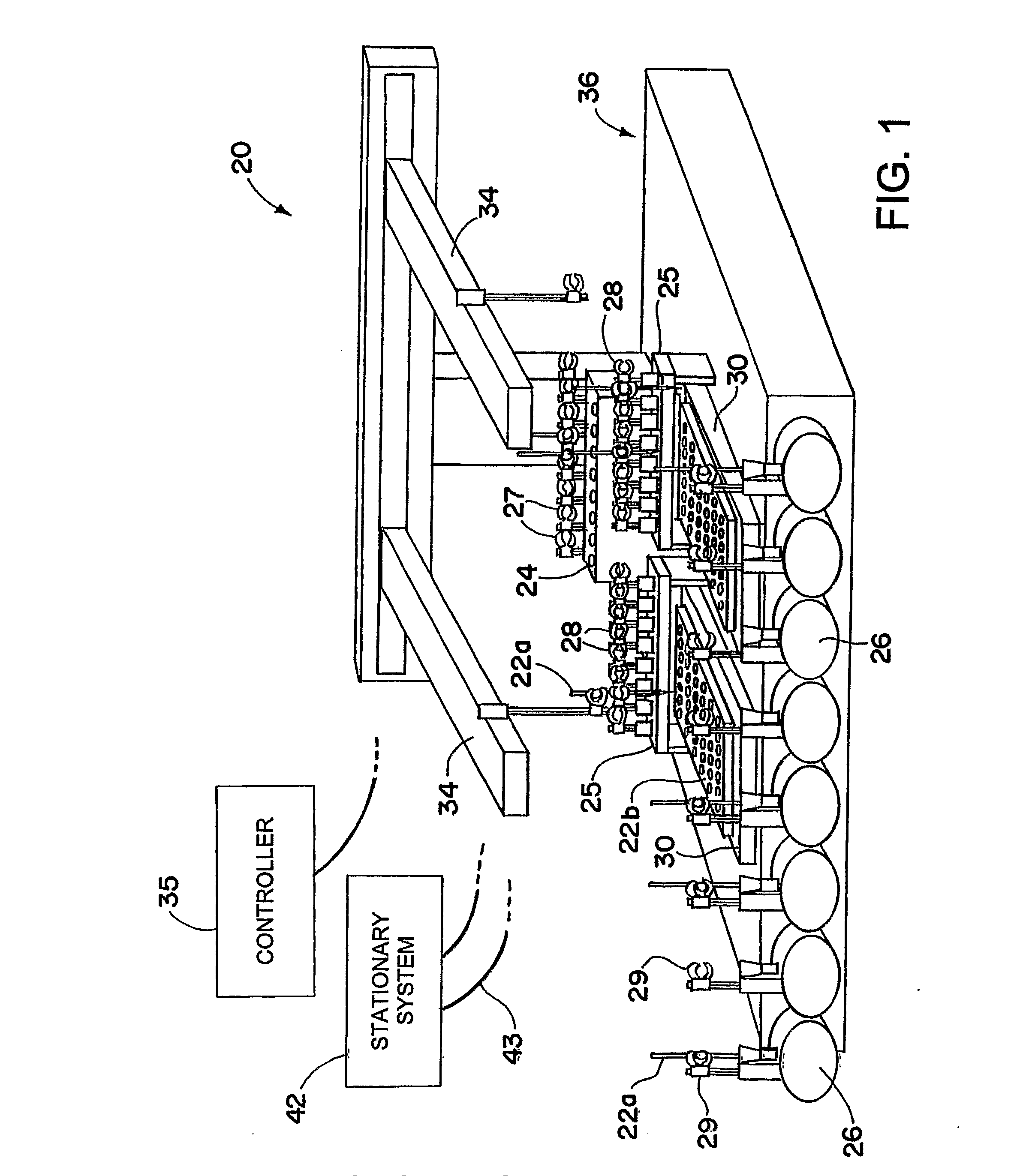
[0030] Referring now in detail to the drawings and initially to FIG. 1, an exemplary embodiment of an analytical system according to the invention is generally denoted by reference numeral 20. The system 20 comprises one or more movable devices 22 for use in the performance of one or more analytical operations, which movable devices may be active devices, such as sampling probes 22a, and / or passive devices, such as trays 22b.

[0031] The system further comprises...


PUM

PropertyMeasurementUnit
movementaaaaaaaaaa
volumeaaaaaaaaaa
poweraaaaaaaaaa

Abstract

An analytical system and method that enables more efficient transport of movable devices (22) among stations (24, 25, 26). According to one aspect of the invention, the system and method permit operational timesharing of a transport mechanism (34) for the movable devices. According to another aspect of the invention, control of the transport mechanism is effected on an event-driven basis. The invention has particular application to an adaptive, motion and fluids system for automating the sample handling / management process associated with analytical processes and especially bioanalytical processes such as introducing samples into LC and HPLC systems.

Description

RELATED APPLICATIONS [0001] This application claims the benefit of U.S. Provisional Application No. 60 / 579,370 entitled “Indiprobe” and filed Jun. 14, 2004, and U.S. Provisional Application No. 60 / 685,833 entitled “Event Driven Laboratory Sample Transport Paradigm” and filed May 31, 2005, both of which are hereby incorporated by reference in their entireties.FIELD OF THE INVENTION [0002] The invention herein described relates generally to robotic handling systems and methods, particularly for analytical applications, more particularly for liquid sample analytical systems, and still more particularly for bioanalytical applications. BACKGROUND [0003] Sample handling robots of various configurations are known in the biotechnology industry. A common feature of such systems is the use of a robotic or other motion control device to either move a fluid aspirating / -dispensing syringe (herein generally referred to as a sampling probe) about a deck of vessels or other deck components like was...

Claims


Application Information

Patent Timeline
Patent Type & Authority Applications(United States)
IPC IPC(8): G01N35/00B66C23/00G01N35/04G01N35/10
CPCG01N35/0099G01N35/1065Y10T436/2575G01N2035/1076G01N2035/0434
Inventor LONDO, THOMAS R.WEISS, ANDREASSCHELBERG, CHARLES C. JR.
Owner PARKER HANNIFIN CORP
Learn More