
Implantable Vascular Access Device

a vascular access device and implantable technology, applied in the direction of medical preparations, infusion needles, other medical devices, etc., can solve the problems of hemodialysis procedures, chronic skin damage at the same location, and deterioration of rubber membranes

Inactive Publication Date: 2007-12-20
NAVILYST MEDICAL
View PDF2 Cites 25 Cited by
  • Summary
  • Abstract
  • Description
  • Claims
  • Application Information

AI Technical Summary

Benefits of technology

[0009] It is an object of the present invention to provide a vascular access device which can withstand a high number of large gauge needle insertions without deterioration.
[0010] It is another object of the present invention to provide a vascular access device which is easily subcutaneously manipulated and which prevents the escape of fluids from the device.
[0011] It is yet another object of the present invention to provide a vascular access device having multiple needle ports thereby reducing the skin trauma caused by repeated needle sticks at the same location.

Problems solved by technology

A major drawback of conventional vascular access devices, particularly those used in hemodialysis procedures, is the deterioration of the rubber membranes as a result of repeated penetration with such large gauge needles.
Additionally, typical vascular access devices provide for only one needle port resulting in chronic breach of the skin at the same location.
This in turn results in increased skin trauma and possible infection.

Method used


Image

  • Implantable Vascular Access Device
  • Implantable Vascular Access Device
  • Implantable Vascular Access Device

Examples


Embodiment Construction

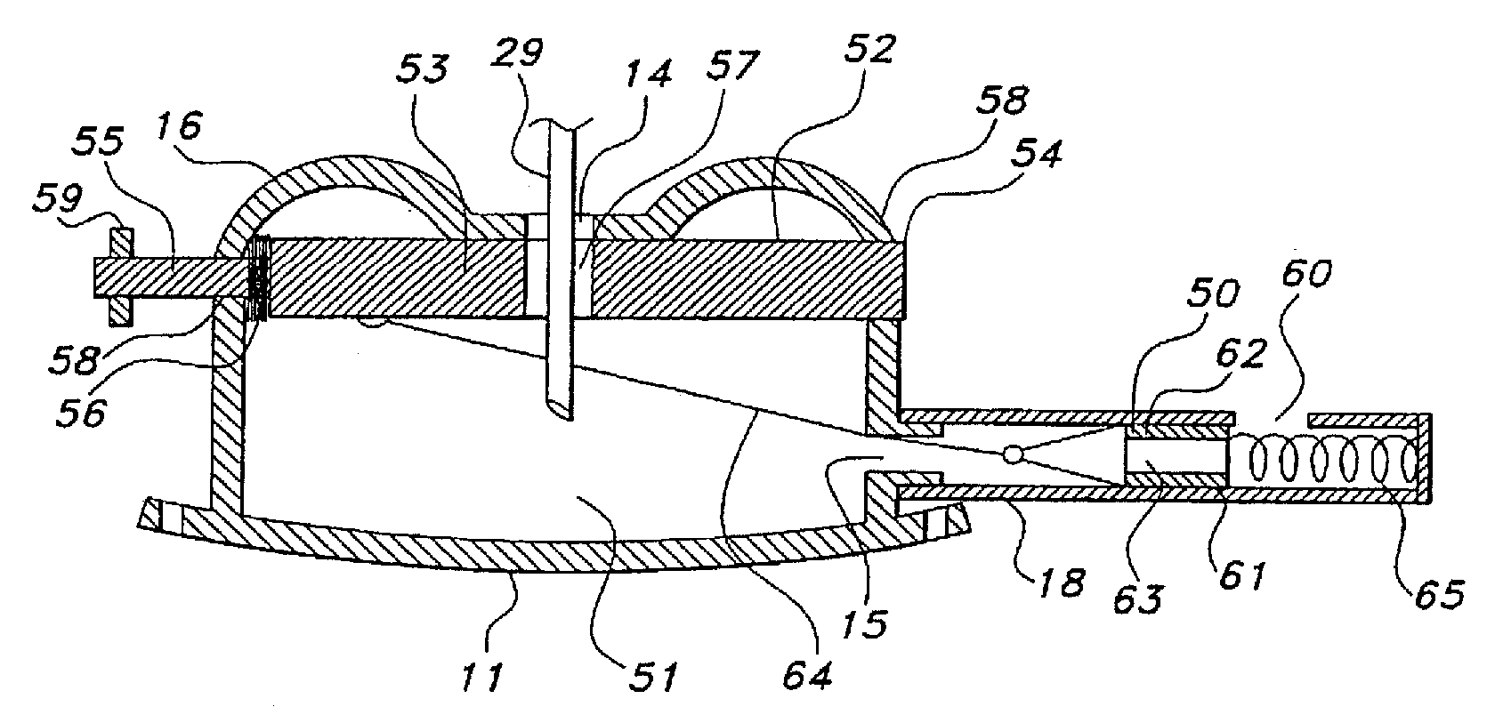
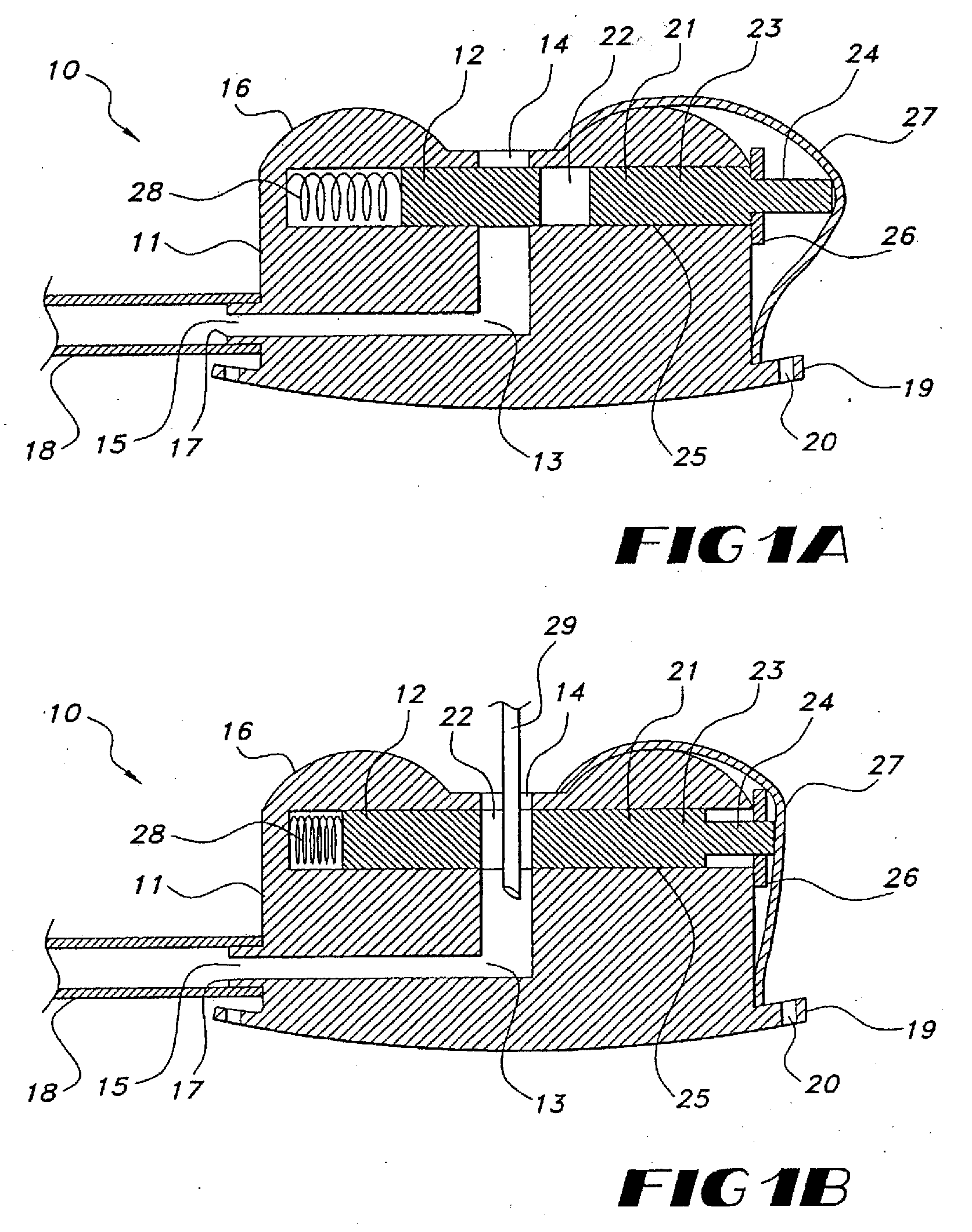
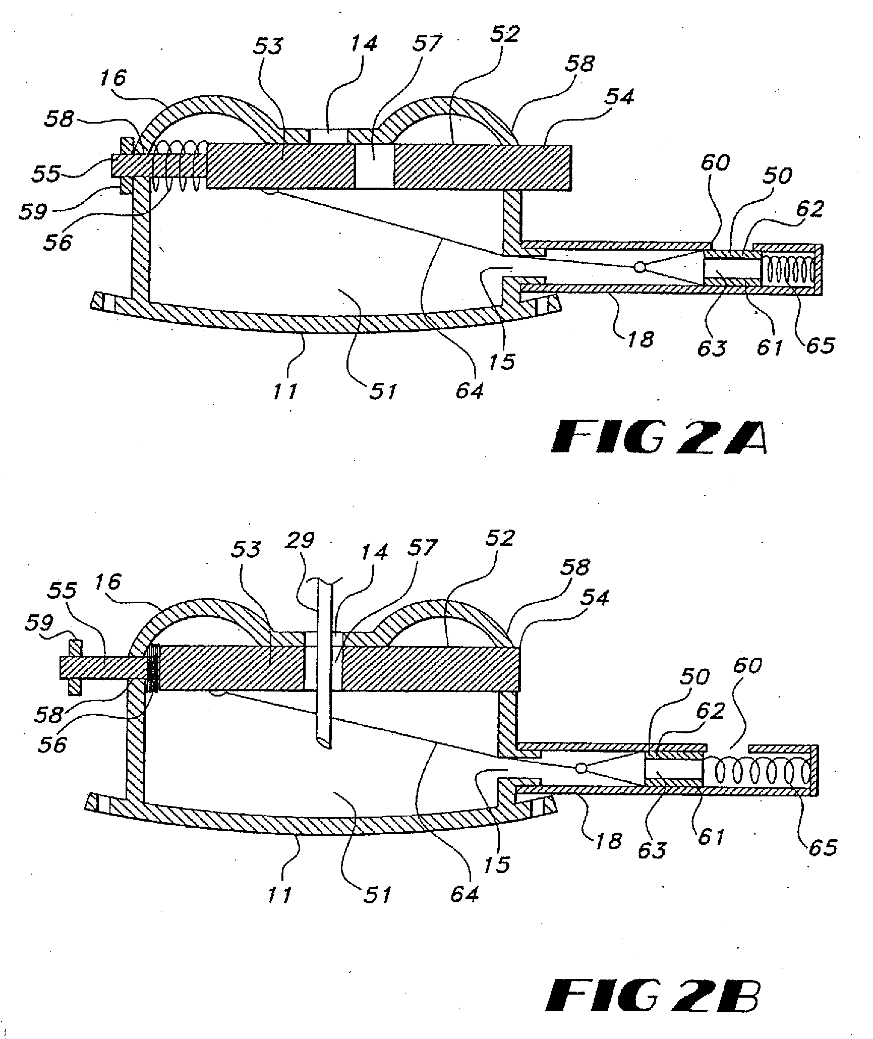
[0022] Referring to FIGS. 1A and 1B, an implantable vascular access device formed in accordance with the present invention is shown. The vascular access device 10 is designed to be surgically implanted under the skin and generally includes a housing 11 and a valve 12. The housing 11 and the valve 12 may be made from any suitable biocompatible material possessing sufficient hardness to resist being damaged or gouged by needles or other devices which will be repeatedly inserted into the device. Plastic constructions are advantageous in that they are inexpensive to fabricate utilizing conventional molding techniques and are available in a variety of biocompatible materials. Surgical metals, however, are also suitable.

[0023] The housing 11 includes an interior chamber 13 formed therein, and an inlet 14 and an outlet 15 extending through an external surface 16 of the housing and communicating with the interior chamber. The outlet 15 may be formed with a cuff 17 to facilitate connection ...


PUM


Abstract

An implantable vascular access device includes a housing having an inlet, an outlet, an interior chamber defined therein and a valve positioned between the inlet and the interior chamber. The valve is subcutaneously manipulated between an open position, in which fluid can flow between the inlet and the interior chamber, and a closed position in which the valve occludes the inlet. The device may include any combination of multiple inlets, outlets and / or interior chambers. In the preferred embodiment, the housing includes two separate interior chambers suitable for the inflow and outflow of a typical hemodialysis procedure. A method for accessing a vascular structure is provided which includes the steps of subcutaneously implanting the device connecting one end of a cannula to the outlet of the device and another end of the cannula to a selected vascular structure. The valve of the device is manipulated to permit fluid communication between the inlet of the device and the selected vascular structure. A needle is introduced through the inlet opening to access the selected vascular structure.

Description

PRIORITY CLAIM [0001] This application is a Continuation application of U.S. patent application Ser. No. 10 / 342,913 filed on Jan. 15, 2003 entitled “Implantable Vascular Access Device” which is a Continuation of U.S. patent application Ser. No. 09 / 957,611 filed on Sep. 20, 2001 entitled “Exhaust Gas Regulator Including a Non-Contact Sensor” and which is a Continuation of U.S. patent application Ser. No. 09 / 398,887 filed on Sep. 20, 1999 entitled “Implantable Vascular Access Device”. The entire disclosures of these prior applications are considered as being part of the disclosure of the accompanying application and hereby expressly incorporated by reference herein.BACKGROUND OF THE INVENTION [0002] 1. Field Of Invention [0003] The present invention relates to implantable vascular access devices used in the delivery and / or withdrawal of fluids to and from the body and more particularly relates to a self-sealing device which permits intermittent vascular access. [0004] 2. Description O...

Claims


Application Information

Patent Timeline
Patent Type & Authority Applications(United States)
IPC IPC(8): A61M39/02A61K9/22A61M37/00
CPCA61M2039/0211A61M39/0208
Inventor SHERRY, JOHN
Owner NAVILYST MEDICAL
Learn More