
Methods and apparatus for guidance systems

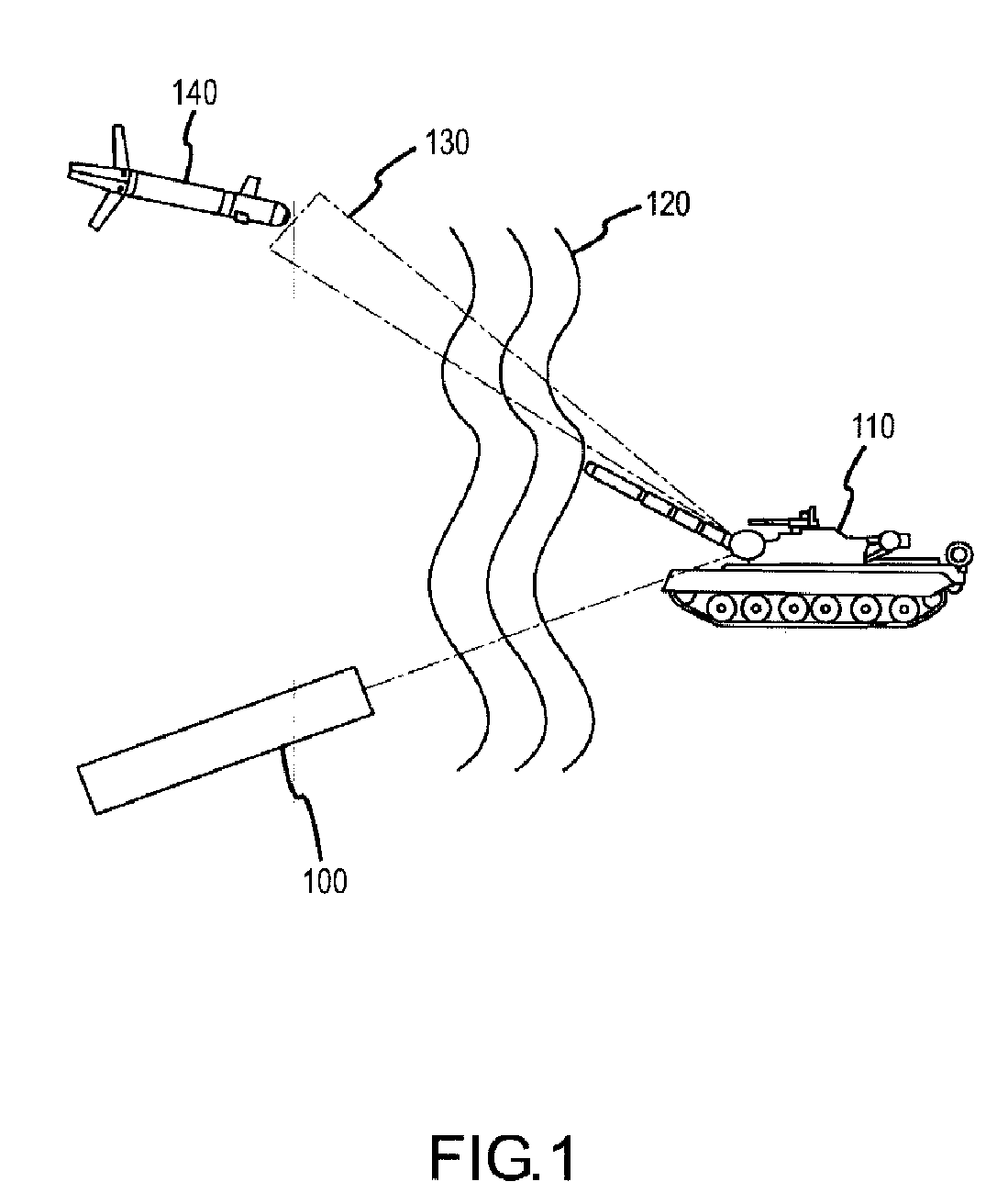
a technology of guidance system and guidance device, applied in the direction of direction/deviation determining electromagnetic system, instruments, optical elements, etc., can solve the problems of non-uniform irradiance, substantial aberration of perceived energy received from a distance, and ordnance that misses the intended targ

Active Publication Date: 2007-12-20
RAYTHEON CO
View PDF8 Cites 20 Cited by
  • Summary
  • Abstract
  • Description
  • Claims
  • Application Information

AI Technical Summary

Benefits of technology

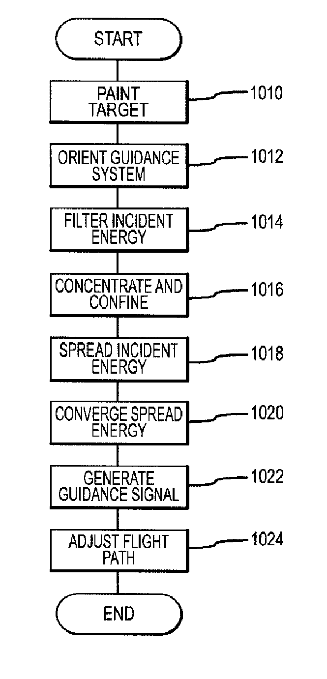
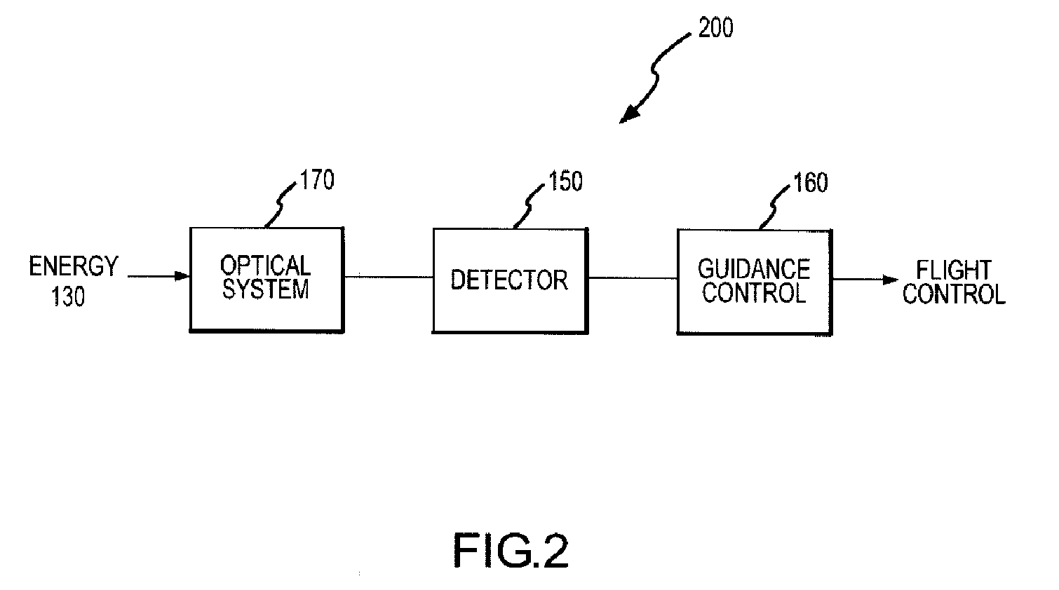
The present invention provides guidance systems for projectiles that use a detector and an optical system to control the path of the projectile. The detector generates signals based on the angle of incident energy, and the optical system spreads and focuses the energy onto the detector. This technology allows for more accurate and efficient guidance of projectiles.

Problems solved by technology

Atmospherically induced scintillation may cause substantial aberrations in perceived energy received from a distance.
Atmospherically induced scintillation effects, however, may produce guidance errors, causing the ordnance to miss the intended target.
Scintillation causes non-uniform irradiance to enter the sensor, which distorts the transfer function.
The performance degradation is pronounced in fixed sensors, i.e., seekers that are not gimbaled.
Unfortunately, the gimbal and supporting actuators substantially add to the cost, complexity and failure susceptibility of the system.

Method used


Image

  • Methods and apparatus for guidance systems
  • Methods and apparatus for guidance systems
  • Methods and apparatus for guidance systems

Examples


Embodiment Construction

[0017] The present invention may be described in terms of functional block components and various processing steps. Such functional blocks may be realized by any number of hardware or software components configured to perform the specified functions and achieve the various results. For example, the present invention may employ various sensors, optical elements, and components, e.g., lenses, detectors, energy concentrators, guidance controllers, and the like, which may carry out a variety of operations and functions. In addition, the present invention may be practiced in conjunction with any number of optical applications and guidance processes, and the system described is merely one exemplary application for the invention. Further, the present invention may employ any number of conventional techniques for trajectory control, target detection, filtering, optical processing, and the like.

[0018] Methods and apparatus for tracking an energy source according to various aspects of the pr...


PUM


Abstract

Methods and apparatus for guidance systems according to various aspects of the present invention operate in conjunction with a projectile including a guidance system having a guidance controller, a detector, and an optical system. The guidance controller controls the path of the projectile according to signals from the detector. The detector generates signals according to an angle of incident energy. The optical system transfers the energy to the detector via a spreader and a condenser. The spreader spreads the incident energy, and the condenser converges the spread energy onto the detector.

Description

CROSS-REFERENCES TO RELATED APPLICATIONS [0001] This application claims the benefit of U.S. Provisional Patent Application No. 60 / 727,181, filed 13 Oct. 2005, is a continuation-in-part of U.S. Nonprovisional patent application Ser. No. 11 / 548,968, filed 12 Oct. 2006, and incorporates the disclosure of each application by reference.BACKGROUND OF THE INVENTION [0002] Atmospherically induced scintillation may cause substantial aberrations in perceived energy received from a distance. In various military applications, missiles and other guided ordnance may be configured to track and engage targets via remote laser designation. Atmospherically induced scintillation effects, however, may produce guidance errors, causing the ordnance to miss the intended target. Scintillation is the variation of energy across a seeker aperture. Scintillation causes non-uniform irradiance to enter the sensor, which distorts the transfer function. [0003] The performance degradation is pronounced in fixed sen...

Claims


Application Information

Patent Timeline
Patent Type & Authority Applications(United States)
IPC IPC(8): F41G7/00
CPCF41G7/226F41G7/2293G01S3/781G02B19/0076G02B5/00G02B19/0014G02B19/0028G01S3/784
Inventor JENKINS, DAVID G.TAYLOR, BYRON B.
Owner RAYTHEON CO
Learn More