
CMOS imager system with interleaved readout for providing an image with increased dynamic range

a technology of dynamic range and image, applied in the field of digital image processing, can solve the problems that the final image of the conventional cmos imager system using two or more frames can require a significant delay, and achieve the effects of increasing dynamic range, cost-effectiveness, and increasing dynamic rang

Active Publication Date: 2007-12-13
IMPERIUM IP HLDG +1
View PDF20 Cites 179 Cited by
  • Summary
  • Abstract
  • Description
  • Claims
  • Application Information

AI Technical Summary

Benefits of technology

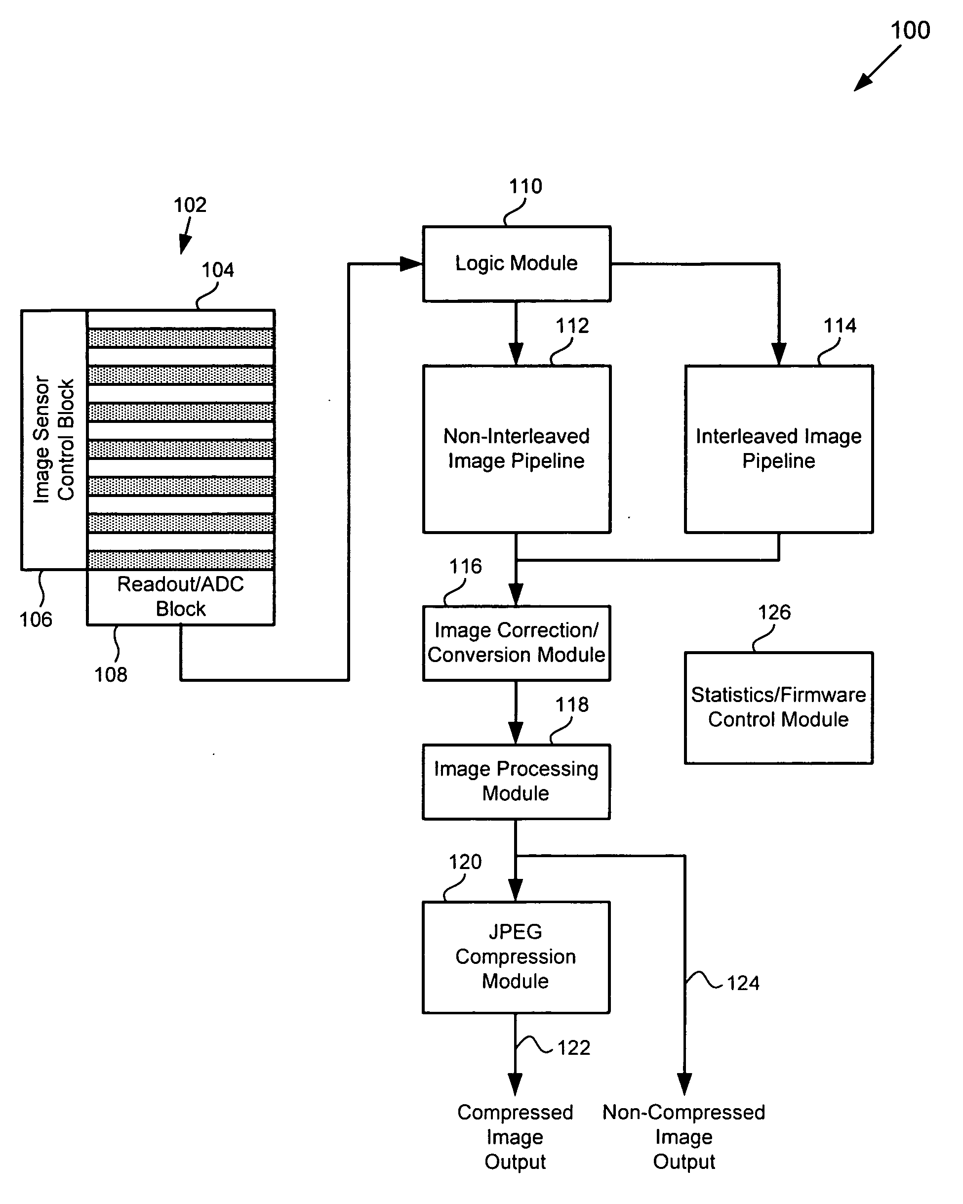
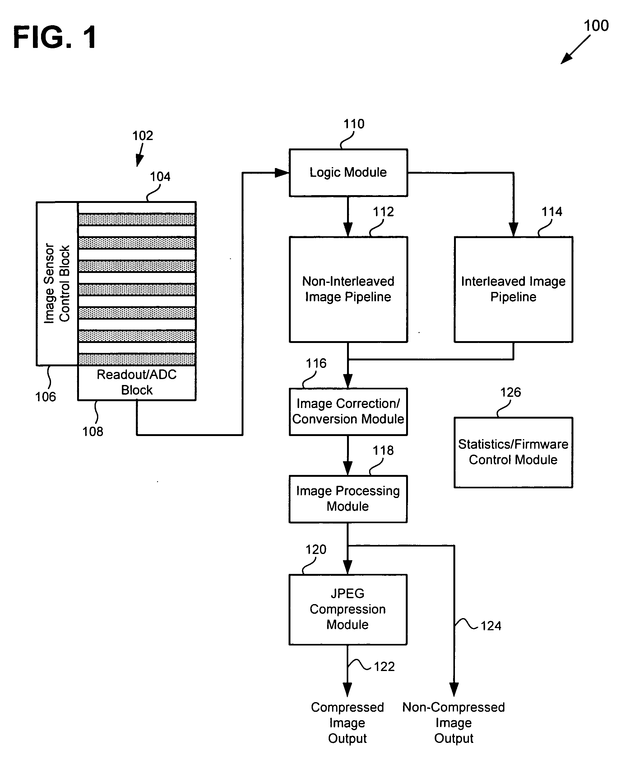
[0009]The present invention is directed to CMOS imager system with interleaved readout for providing an image with increased dynamic range. More specifically, the invention provides a cost-effective CMOS imager system with an image sensor having an interleaved readout for providing a viewable image with increased dynamic range. The invention also provides a CMOS imager system that provides an increased dynamic range image with reduced motion artifacts and reduced latency compared to a conventional CMOS imager system that uses information from multiple successive frames.
[0012]An additional benefit of the interleaved CMOS wide dynamic range imager system is the reduction of motion artifacts since a single frame contains information from two or more exposures which are executed in the shortest possible time. The invention's CMOS imager system provides a further benefit of forming the increased dynamic range image with minimal latency through pipeline processing of the image data. In contrast, conventional CMOS imager systems using two or more frames can require a significant delay before the final image is formed in post processing from one or more stored frames.

Problems solved by technology

In contrast, conventional CMOS imager systems using two or more frames can require a significant delay before the final image is formed in post processing from one or more stored frames.

Method used


Image

  • CMOS imager system with interleaved readout for providing an image with increased dynamic range
  • CMOS imager system with interleaved readout for providing an image with increased dynamic range
  • CMOS imager system with interleaved readout for providing an image with increased dynamic range

Examples


Embodiment Construction

[0038]The present invention is directed to CMOS imager system with interleaved readout for providing an image with increased dynamic range. Although the invention is described with respect to specific embodiments, the principles of the invention, as defined by the claims appended herein, can obviously be applied beyond the specifically described embodiments of the invention described herein. Moreover, in the description of the present invention, certain details have been left out in order to not obscure the inventive aspects of the invention. The details left out are within the knowledge of a person of ordinary skill in the art.

[0039]The drawings in the present application and their accompanying detailed description are directed to merely example embodiments of the invention. To maintain brevity, other embodiments of the invention which use the principles of the present invention are not specifically described in the present application and are not specifically illustrated by the pr...


PUM


Abstract

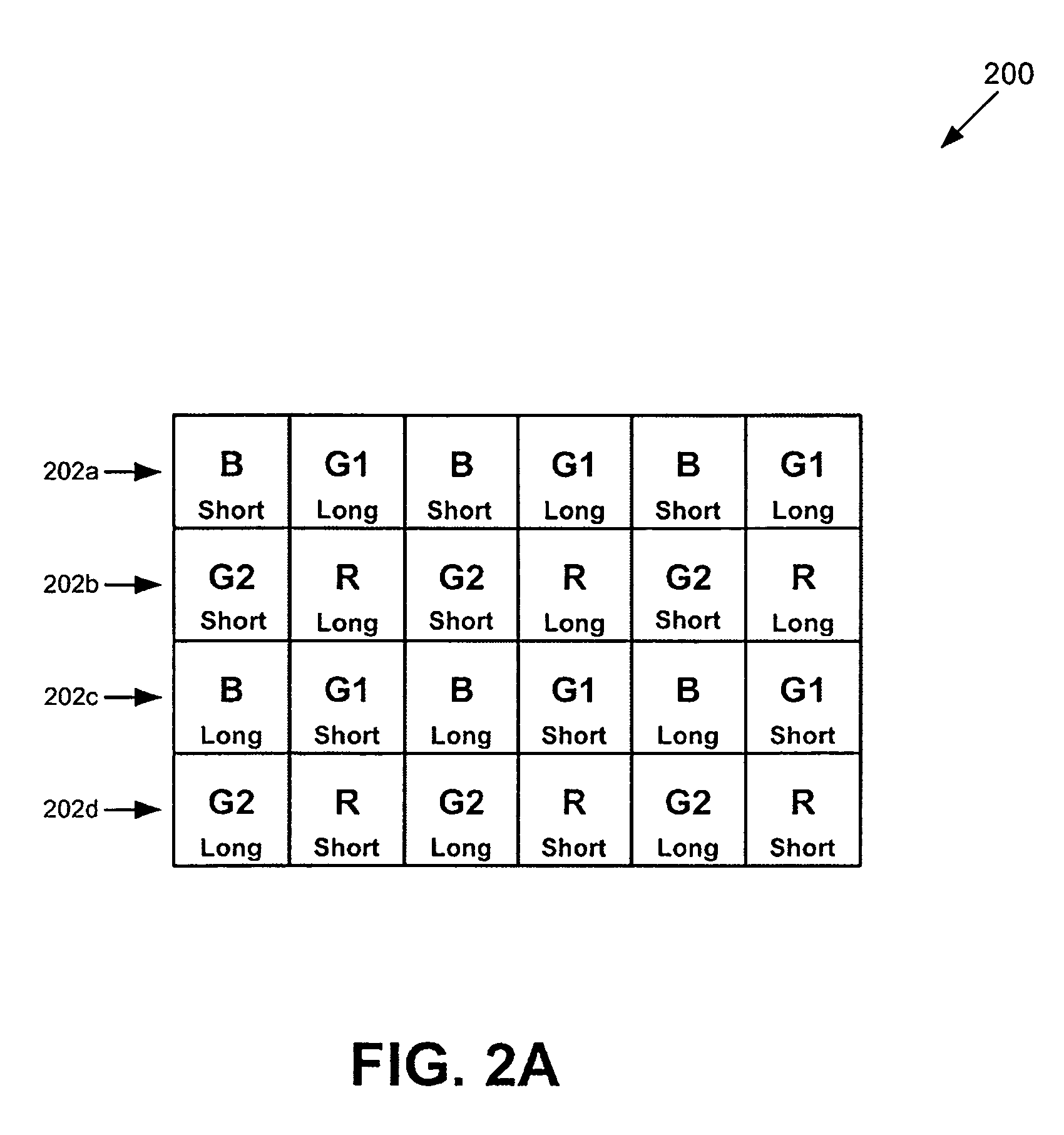
There is provided a CMOS imager system for providing a viewable image having increased dynamic range including an image sensor including a number of sets of pixels. Each set of pixels is configured to receive one of a number of exposures and to generate image data corresponding to the received exposure in the interleaved mode. The image sensor is configured to operate in either an interleaved mode or a non-interleaved mode and to output the image data generated by each set of pixels as a frame of interleaved image data in the interleaved mode. The imager system further includes an interleaved image pipeline in communication with the image sensor, where the interleaved image pipeline is configured to receive the interleaved image data from the image sensor, combine the image data generated by each set of pixels corresponding to one of the exposures to form the viewable image.

Description

RELATED APPLICATIONS[0001]The present application claims the benefit of U.S. provisional application Ser. No. 60 / 809,890, filed May 31, 2006, which is hereby fully incorporated by reference in the present application.BACKGROUND OF THE INVENTION[0002]1. Field of the Invention[0003]The present invention is generally in the field of digital image processing. More specifically, the present invention is in the field of CMOS imager systems for digital image capture and image processing.[0004]2. Related Art[0005]Mobile imaging devices, such as cell phone cameras, require very small size cameras to capture a target scene and output an image that corresponds to the target scene. As pixel resolution is increased and camera size is held constant or reduced in mobile imaging devices, the pixel size for imagers, such as complementary metal oxide semiconductor (CMOS) imagers, in the cameras is reduced. As a result of pixel size reduction, the dynamic range of the image provided by the CMOS imager...

Claims


Application Information

Patent Timeline
IPC IPC(8): H04N5/228H04N5/335
CPCH04N5/23245H04N5/35554H04N5/2355H04N5/235H04N23/667H04N23/70H04N23/741H04N25/583
Inventor MANN, RICHARD A.BENCUYA, SELIMLUO, JIAFUGRIGORIEV, ALEXANDRE G.ZHANG, HENGSHI, MIAOHONGBLAIR, ROBERTSAFAI, MAX
Owner IMPERIUM IP HLDG
Learn More