Resistive torsional mode damping system and method
- Summary
- Abstract
- Description
- Claims
- Application Information
AI Technical Summary
Benefits of technology
Problems solved by technology
Method used
Image
Examples
Embodiment Construction
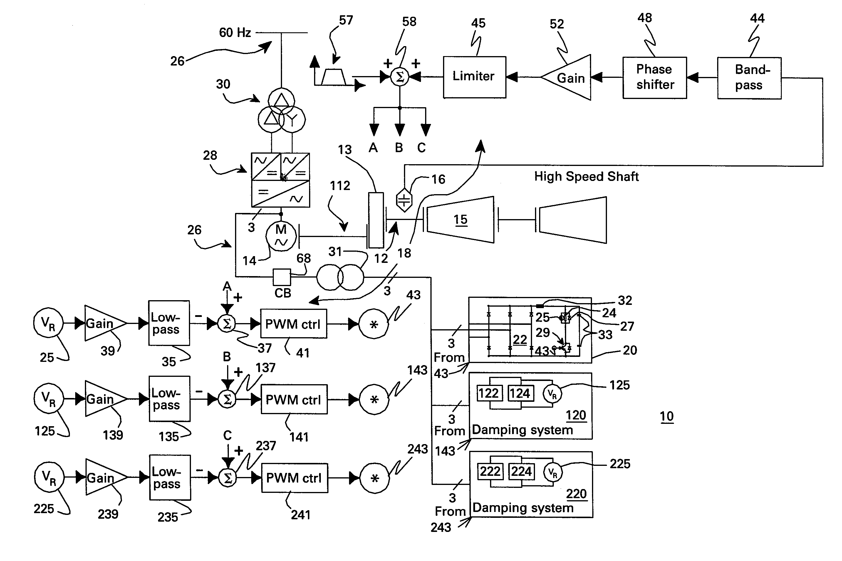
[0018]FIG. 1 is a block diagram of a resistive torsional mode damping system 10 for a shaft 12 of a machine 14. Damping system 10 comprises a sensor 16 configured for sensing a signal representative of torque on shaft 12 and a controller 18 configured for using the sensed signal for detecting a presence of a torsional vibration on shaft 12 corresponding to a natural frequency of the shaft assembly and for generating control signals for damping the torsional vibration (which is shown in two separate portions 1 of FIG. 1 for purposes of fitting FIG. 1 on one sheet). Damping system 10 further comprises a damper 20 comprising a damping converter 22 and resistor 24 coupled to a DC output of damping converter 22. The damping converter is coupled to machine 14 through a power bus 26 (sometimes referred to as a bus bar or grid). The damping converter typically has power rating on the order of less than or equal to about five percent of a nominal power of machine 14. As used herein “converte...
PUM
 Abstract
Description
Claims
Application Information
 - R&D
- Intellectual Property
- Life Sciences
- Materials
- Tech Scout
- Unparalleled Data Quality
- Higher Quality Content
- 60% Fewer Hallucinations
Browse by: Latest US Patents, China's latest patents, Technical Efficacy Thesaurus, Application Domain, Technology Topic, Popular Technical Reports.
© 2025 PatSnap. All rights reserved.Legal|Privacy policy|Modern Slavery Act Transparency Statement|Sitemap|About US| Contact US: help@patsnap.com


