Eureka AIR delivers breakthrough ideas for toughest innovation challenges, trusted by R&D personnel around the world.

Electric power supply apparatus and method of synchronously operating power converter

a technology of electric power supply and synchronous operation, which is applied in the direction of electric generator control, generation protection through control, instruments, etc., can solve the problems of automatic limitation of the operation of the load on the electric power supply apparatus

Inactive Publication Date: 2007-11-29
EBARA CORP +1
View PDF3 Cites 176 Cited by
  • Summary
  • Abstract
  • Description
  • Claims
  • Application Information

AI Technical Summary

Benefits of technology

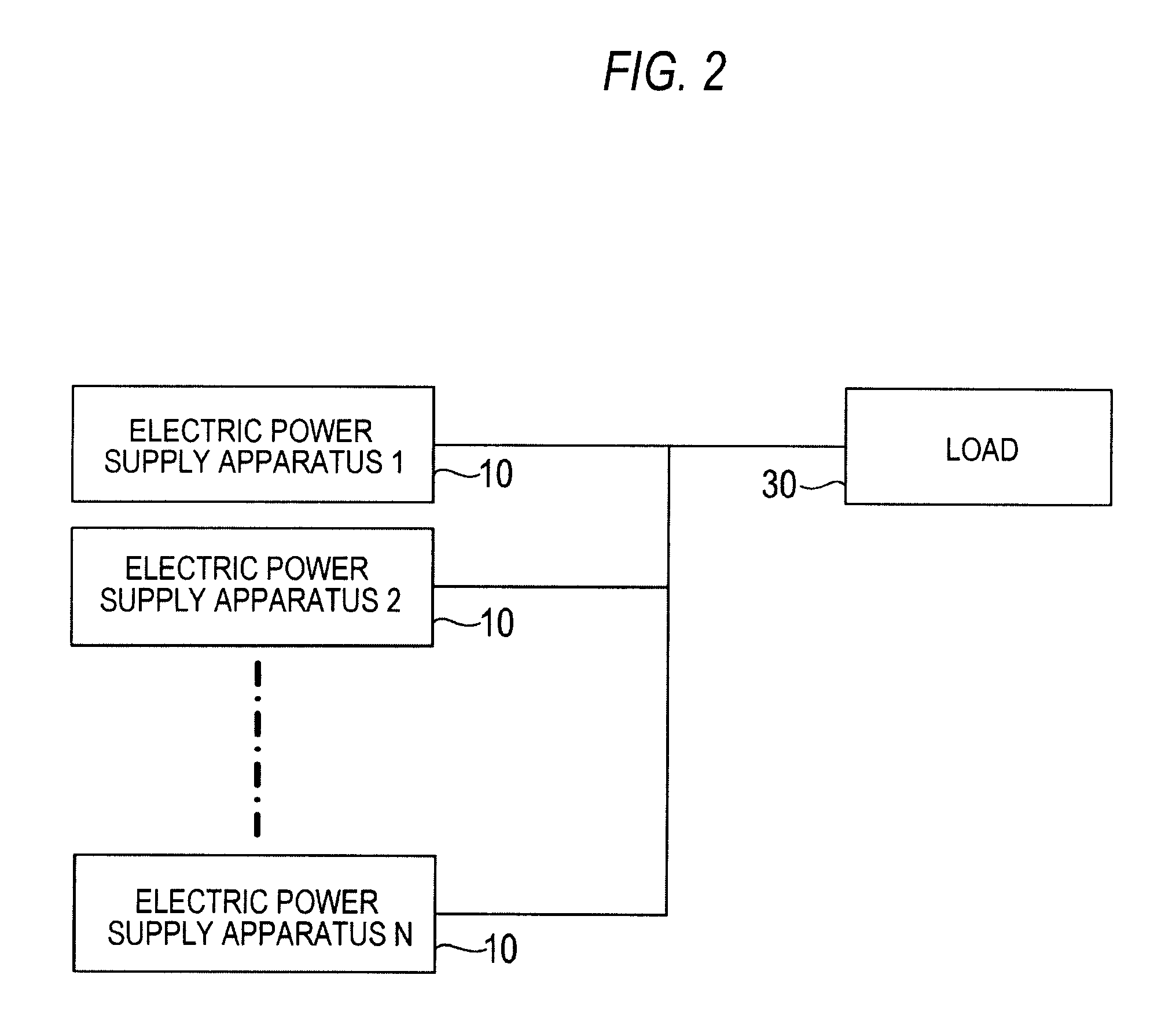
"The present invention provides an electric power supply apparatus for use in an electric power supply system comprising multiple unitized electric power supply apparatuses connected in parallel. Each unitized electric power supply apparatus includes an electric generator and a power converter with an output voltage and current characteristic that determines the load sharing rate of the electric generator. The apparatus also includes a controller with output voltage and current characteristics that automatically limit the load sharing rate of the electric generator when the load demand exceeds its power generation capability. The invention also provides a method for synchronizing the output voltage of multiple power converters connected in parallel without the need for a synchronizing signal. The technical effects of the invention include improved load sharing, reduced load demand on the electric generator, and improved reliability of the overall electric power supply system."

Problems solved by technology

Consequently, before the electric generator is overloaded, the load on the electric power supply apparatus can be limited and can be distributed to other electric power supply apparatus.
Therefore, the operation of the electric power supply apparatus is automatically limited within the range of the power generation capability of the electric power supply apparatus and can be continued.

Method used


Image

  • Electric power supply apparatus and method of synchronously operating power converter
  • Electric power supply apparatus and method of synchronously operating power converter
  • Electric power supply apparatus and method of synchronously operating power converter

Examples


Embodiment Construction

[0046]An electric power supply apparatus according to embodiments of the present invention will be described in detail below with reference to the accompanying drawings. The same or corresponding members or elements are denoted by the same reference numerals throughout views and will not be described repetitively.

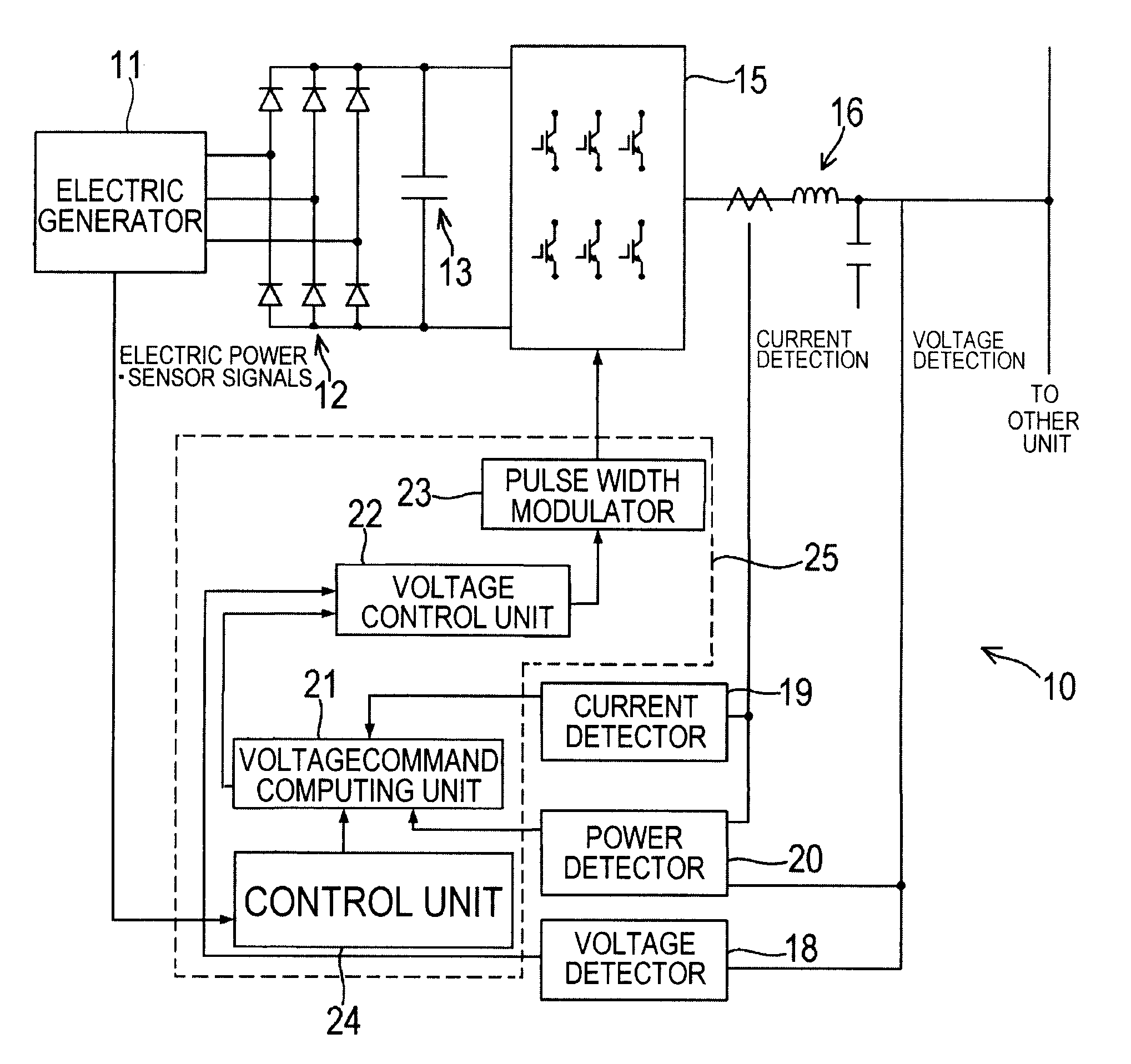
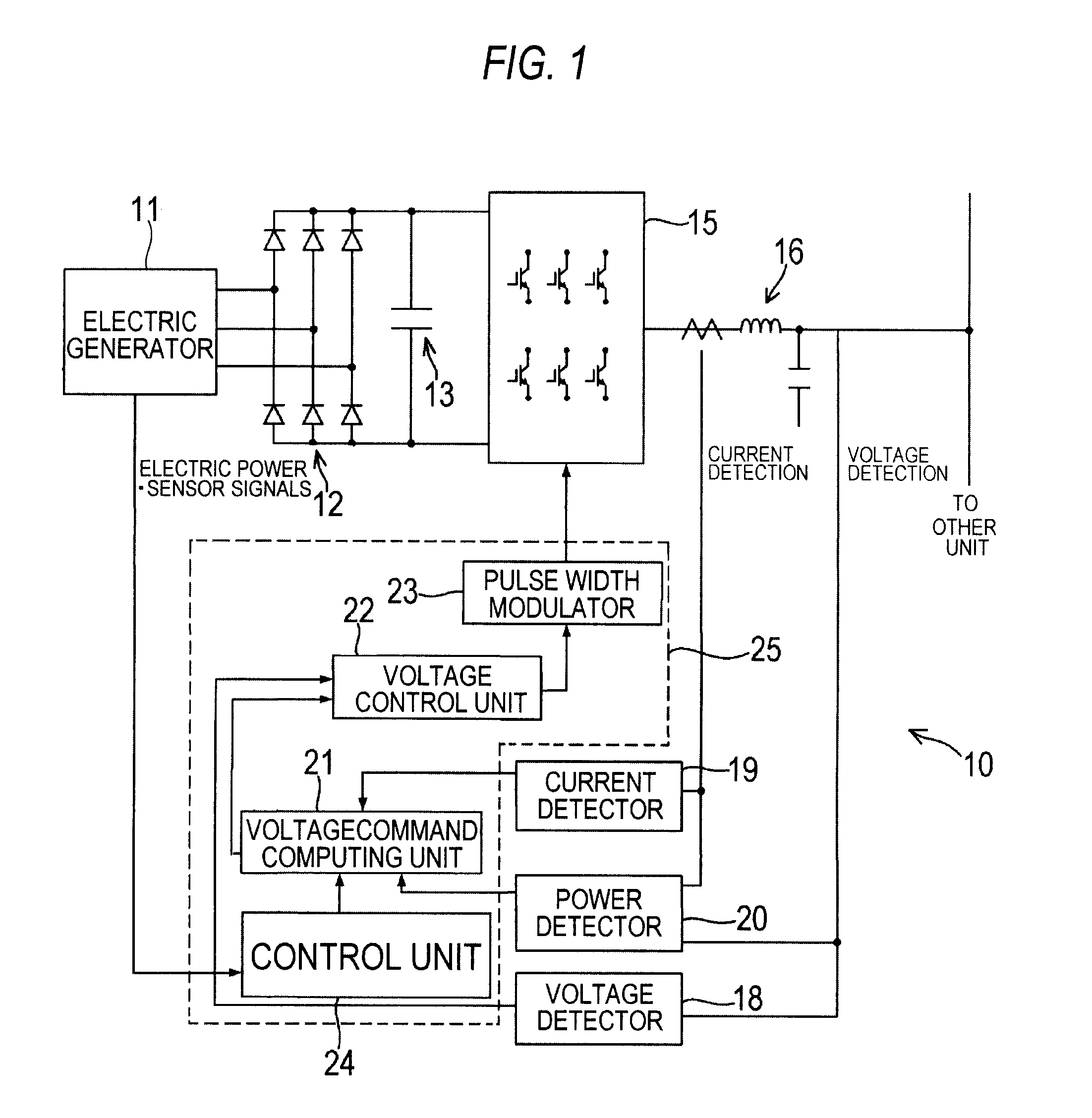
[0047]FIG. 1 shows an electric power supply apparatus according to an embodiment of the present invention. As shown in FIG. 1, an electric power supply apparatus, generally denoted by 10, has an electric generator 11 in the form of a distributed electric generator such as a gas turbine generator, for example. AC electric power (alternating-current power) generated by the electric generator 11 is rectified by a converter 12 such as a full-wave rectifying circuit into DC electric power (direct-current power) which is stored in a capacitor (DC power supply) 13 and is then converted by an inverter 15 into AC electric power (alternating-current power) having a required frequency...


PUM


Abstract

An electric power supply apparatus includes a distributed power generator such as a gas turbine generator and a power converter such as an inverter apparatus for converting electric power generated by the distributed power generator into AC electric power (alternating-current power) having a required frequency and a required voltage and supplying the AC electric power to a load. The electric power supply apparatus further includes a control unit having output voltage vs. output current characteristics for determining an output voltage corresponding to an output current of the power converter. The output voltage vs. output current characteristics has a first dropping characteristic for causing output electric power of the electric generator to be limited, between a first output current exceeding a power generation capability of the electric generator and a second output current exceeding a power converting capability of the power converter.

Description

BACKGROUND OF THE INVENTION[0001]1. Field of the Invention[0002]The present invention relates to a unitized electric power supply apparatus comprising a distributed power generator such as a gas turbine generator and a power converter such as an inverter apparatus for converting electric power generated by the distributed power generator into AC electric power (alternating-current power) having a required frequency and a required voltage and supplying the AC electric power to a load, and more particularly to an electric power supply apparatus for use in an electric power supply system comprising a plurality of electric power supply apparatuses connected in parallel and operable in a parallel-run mode for supplying electric power to a load disconnected from a commercial power supply system.[0003]Further, the present invention relates to a method of synchronizing output voltages of a plurality of inverter apparatuses (power converters) connected in parallel when the inverter apparatus...

Claims


Application Information

Patent Timeline
Patent Type & Authority Applications(United States)
IPC IPC(8): G05F1/10H02J3/12
CPCH02P2101/10H02P9/006
Inventor KATAOKA, TADASHISAKATA, SHIGERUOZAWA, TAKAHIDETSUKAGOSHI, ISAODAI, ZHENG
Owner EBARA CORP
Why Eureka
Eureka Blog
Learn More