Eureka AIR delivers breakthrough ideas for toughest innovation challenges, trusted by R&D personnel around the world.

Method and apparatus for distributed generator planning

Inactive Publication Date: 2011-05-05
ENPHASE ENERGY
View PDF3 Cites 17 Cited by
  • Summary
  • Abstract
  • Description
  • Claims
  • Application Information

AI Technical Summary

Problems solved by technology

Use of distributed generators (DGs) to produce energy from renewable resources is steadily gaining commercial acceptance due to the rapid depletion of existing fossil fuels and the increasing costs of current methods of generating power.

Method used


Image

  • Method and apparatus for distributed generator planning
  • Method and apparatus for distributed generator planning
  • Method and apparatus for distributed generator planning

Examples


Embodiment Construction

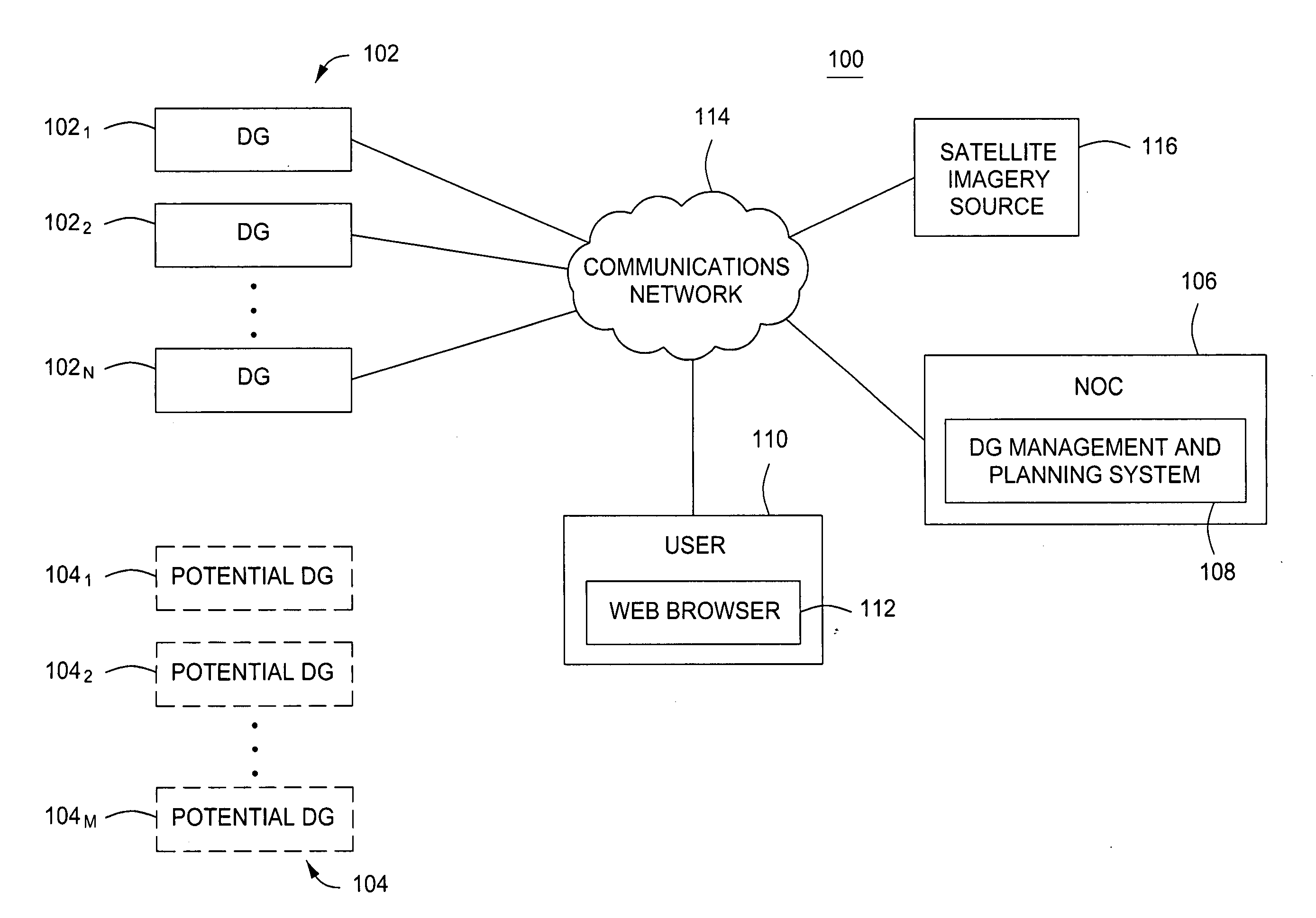
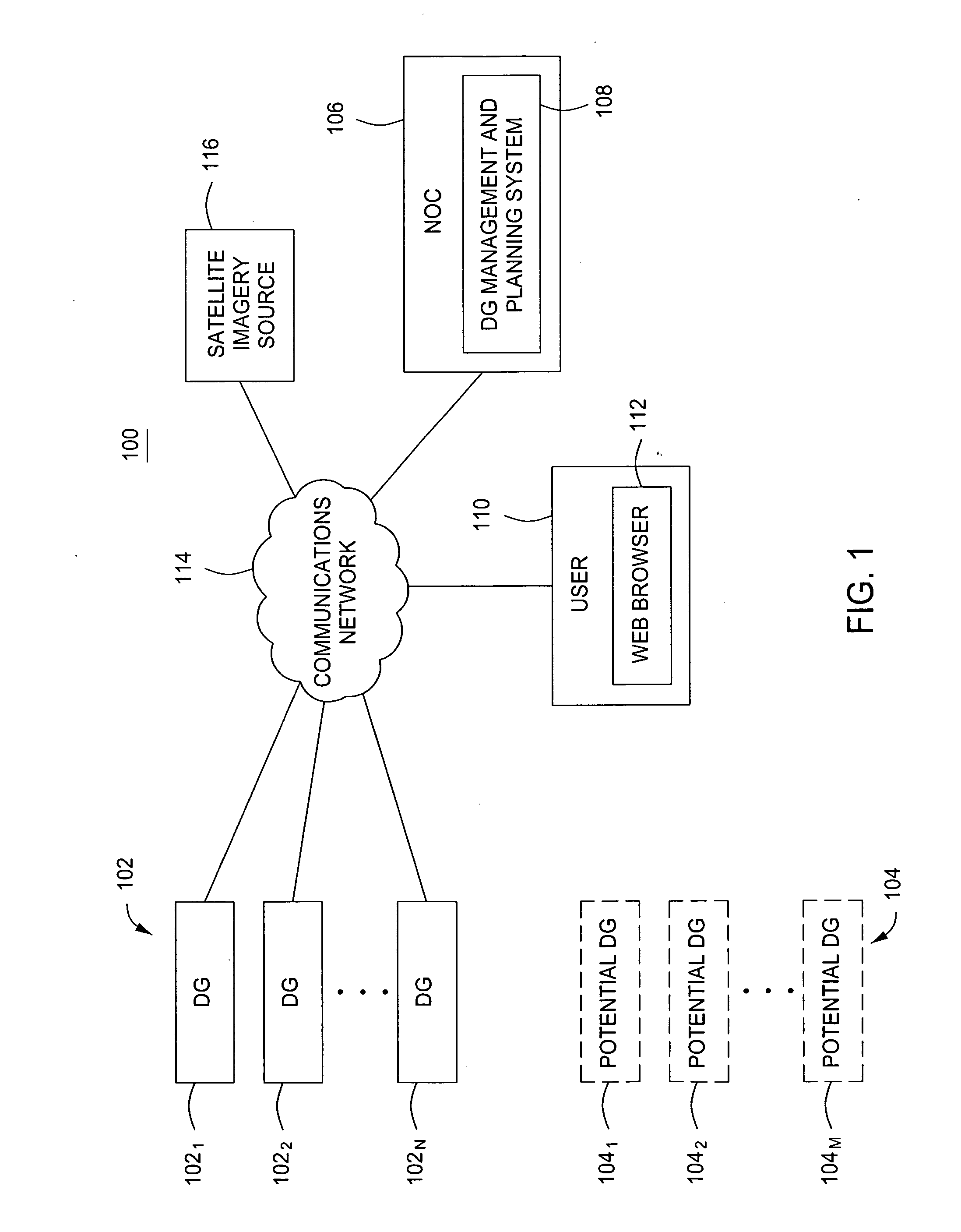
[0017]FIG. 1 is a block diagram of a system 100 for managing and planning distributed generators (DGs) in accordance with one or more embodiments of the present invention. The system 100 comprises a plurality of distributed generators (DGs) 1021, 1022, . . . 102n, (hereinafter, DGs 102), a plurality of potential DGs 1041, 1042, . . . , 104m, (hereinafter, potential DGs 104), a network operations center (NOC) 106, a user 110, and a satellite imagery source 116, all communicatively coupled via a communications network 114, e.g., the Internet.

[0018]The DGs 102 are DGs that are either in the process of being installed and turned-up for operation or are fully installed and operational. Each DG 102, once fully installed and operational, generates power from one or more renewable resource, such as solar energy, wind energy, hydroelectric energy, and the like. The generated power may be used to operate appliances in a home or business, coupled to a commercial power grid and sold to the comm...


PUM


Abstract

A method and apparatus for distributed generator (DG) planning. In one embodiment, the apparatus comprises (i) at least one interface for sizing a potential DG; (ii) at least one interface for designing the potential DG; and (iii) at least one interface for generating a proposal for the potential DG.

Description

CROSS-REFERENCE TO RELATED APPLICATIONS[0001]This application claims benefit of U.S. provisional patent application Ser. No. 61 / 279,844, filed Oct. 27, 2009, which is herein incorporated in its entirety by reference.BACKGROUND OF THE INVENTION[0002]1. Field of the Invention[0003]Embodiments of the present disclosure relate generally to distributed generators (DGs) and, more particularly, to a method and system for planning DGs.[0004]2. Description of the Related Art[0005]Use of distributed generators (DGs) to produce energy from renewable resources is steadily gaining commercial acceptance due to the rapid depletion of existing fossil fuels and the increasing costs of current methods of generating power. One such type of DG may be utilized within a solar power system, where each DG in the solar power system is comprised of photovoltaic (PV) modules that convert solar energy received from the sun into a direct current (DC). A power converter then converts the DC current from the PV m...

Claims


Application Information

Patent Timeline
IPC IPC(8): G06Q30/00
CPCG06Q10/06G06Q50/06G06Q30/0633G06Q10/0631
Inventor LEE, LEESAZAZUETA-HALL, ILEN
Owner ENPHASE ENERGY
Why Eureka
Eureka Blog
Learn More