
Appliance and Method for Measuring an Emg Signal

Inactive Publication Date: 2007-11-22
UNIV LIBRE DE BRUXELIES
View PDF11 Cites 42 Cited by
  • Summary
  • Abstract
  • Description
  • Claims
  • Application Information

AI Technical Summary

Benefits of technology

[0046] Through the use of the appliance according to the present invention for this type of application, it is observed that the resolution is maintained, even when the amplitude of the EMG signal decreases over time. Moreover, the invention helps to solve the problem of the signal-to-noise ratio decrease related to the decrease in the amplitude of the EMG signal during curarization. More generally, the invention allows effective measurement in a noisy environment (electroma

Problems solved by technology

This evaluation of the muscle relaxation is confronted with a certain number of difficulties of measurement: a decrease in the amplitude of the EMGs during curarization; a noisy environment, in particular through electromagnetic pollution; the requirement that the initialization phase, that is to say the time for setting up the electrodes and calibrating the appliance, relatively short.
In most cases, the measurements are marred by a stimulation artifact.
Moreover, for all these appliances or methods, a loss of signal is obtained when the EMGs decrease in amplitude.

Method used


Image

  • Appliance and Method for Measuring an Emg Signal
  • Appliance and Method for Measuring an Emg Signal
  • Appliance and Method for Measuring an Emg Signal

Examples


Embodiment Construction

1. Presentation of the Appliance

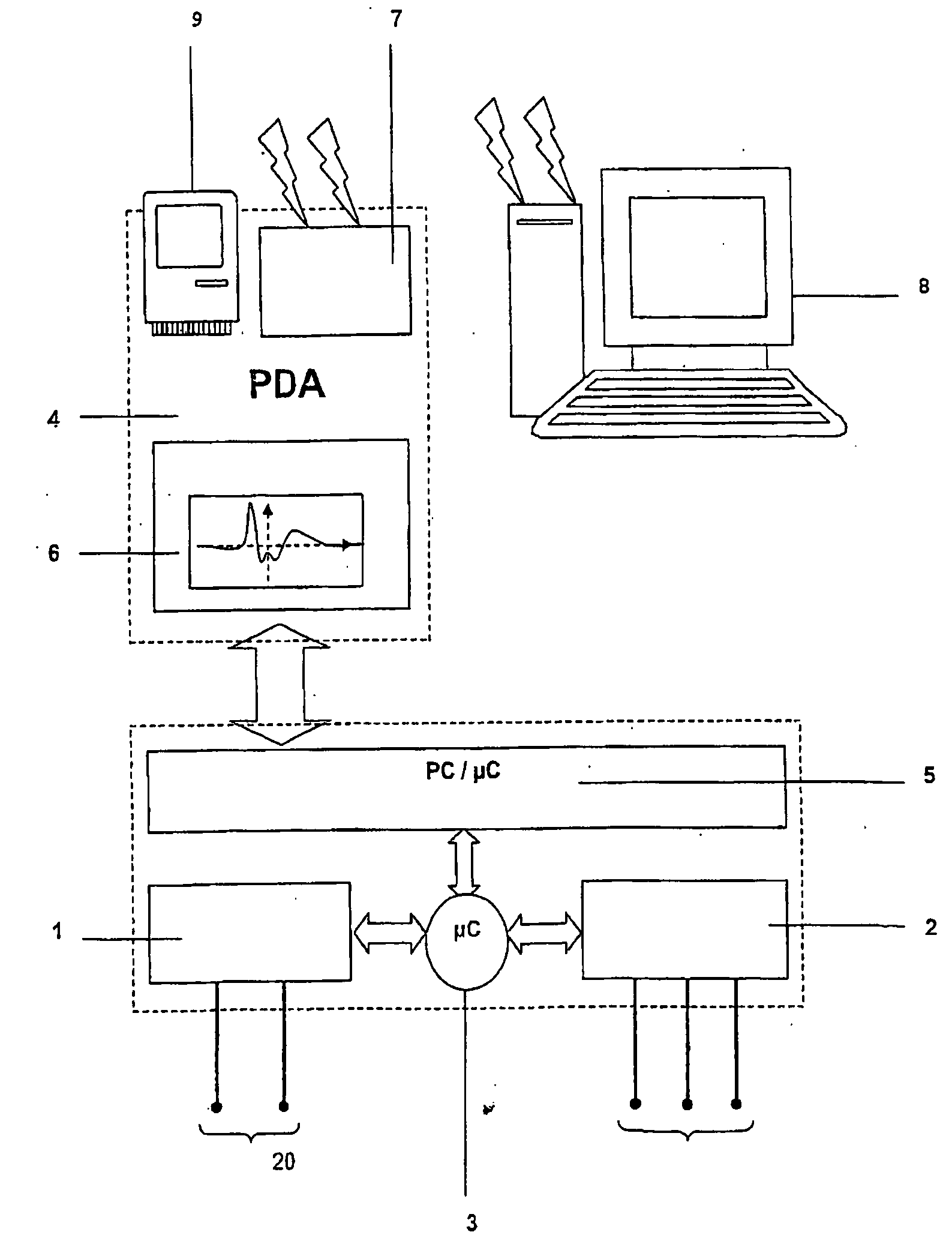
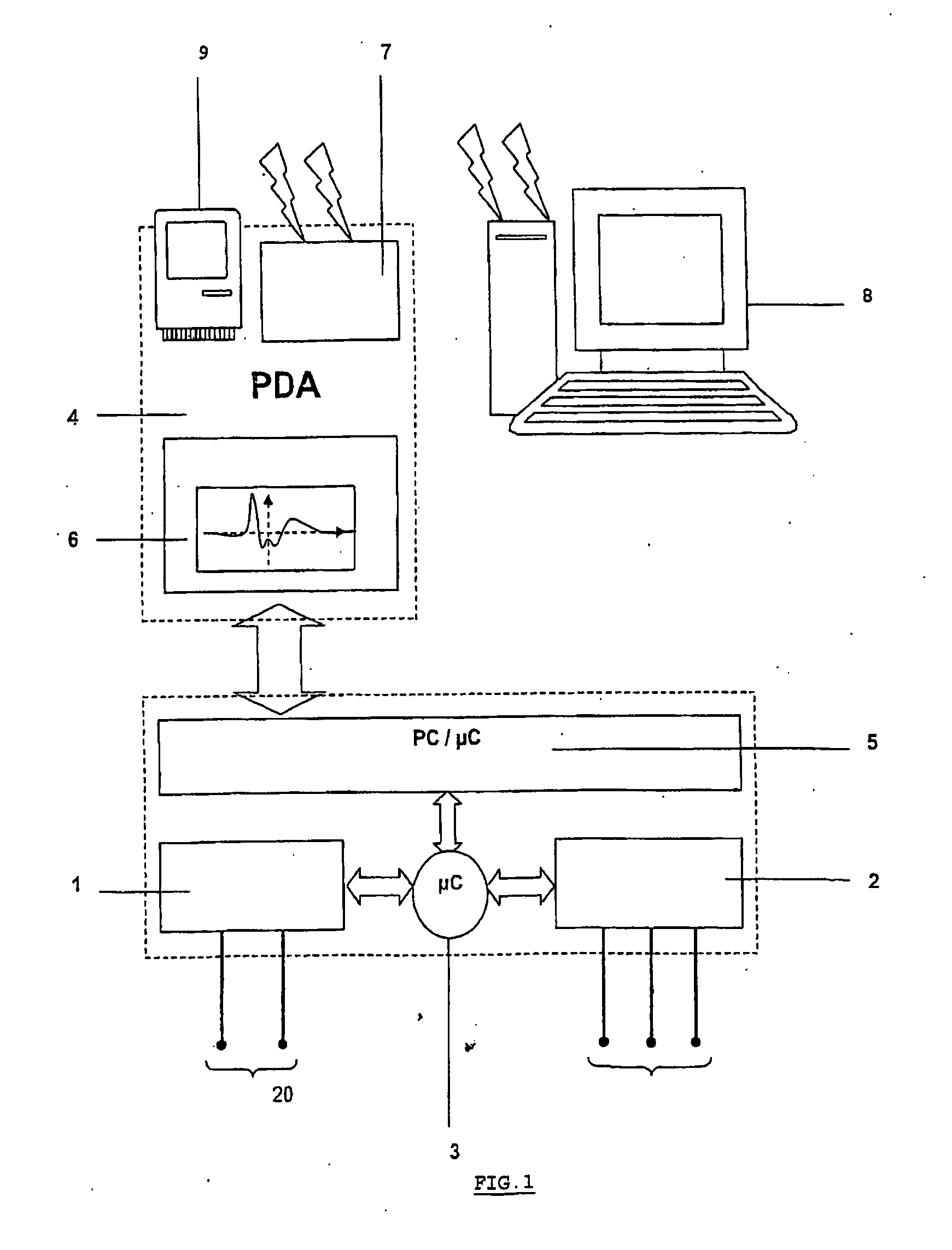
[0087] The appliance according to the invention, illustrated diagrammatically in FIG. 1, comprises a current source 1 linked to stimulation electrodes (20) allowing the excitation of a peripheral motor nerve and an acquisition chain 2 specially adapted to the measurement of the electromyographic potentials, spontaneous and / or evoked by way of measurement electrodes 31.

[0088] At the heart of the system is found a microcontroller 3 which has to ensure the driving and the synchronization of the various modules of the system in real time as well as the communication with the computer 4 via a standardized interface 5 (RS-232, USB, RS-485, etc.).

[0089] The EMG signal and / or its parameters may be viewed on the display screen 6.

[0090] Although the system may be driven from any workstation comprising a standard communication port (RS-232, USB, RS-485, etc.), it is advisable to preferably use a PDA (Personal Digital Assistant) 4 to effect the user interfac...


PUM


Abstract

The present invention relates to an appliance for the direct measurement, display, processing and transmission, remotely, of electromyographic signals (EMG) comprising: an electrical stimulator (1) comprising electrodes for the excitation of a peripheral motor nerve; a pair of electrodes (31), for the acquisition of the EMG response at the level of the muscle associated with this peripheral nerve; an acquisition chain (2) driven by a micro-controller (3, 39), presenting means of conditioning of the input signal, comprising at least one differential preamplifier (22, 33), a bandpass filter (25, 34) and an analog / digital converter (ADC) (26, 310), said acquisition chain (2) being linked, via a standardized interface (5), to a computer (4) comprising means of storage (9) and of display of the EMG signals acquired as well as an executable program for effecting the interface with the user (6) and utilizing the data stored; characterized in that the acquisition chain (2) comprises means of automatic adjustment of the amplification gain of the EMG signal (23, 24, 311, 38), via the microcontroller, in such a way that the EMG signal covers the largest possible part of the input voltage span of the ADC (26, 310), hence with conservation of resolution, when the amplitude of the EMG signal decreases.

Description

SUBJECT OF THE INVENTION [0001] The present invention relates to a novel appliance and to a novel method of measuring electromyograms. [0002] When a muscle is under activity, it is possible to gather a low amplitude (bio)electrical signal by placing electrodes on it. All these signals, taking the form of electrical potentials, are called an electro-myogram (EMG). [0003] The aim of an EMG analysis is to obtain information on the state and the functioning of the muscles through quantification of the electromuscular activity. This measurement is performed by means of electrodes applied on or under the skin. A signal is detected, manifesting the activity of the subjacent muscle. BACKGROUND AND PRIOR ART [0004] Electro-stimulation is known and consists in exciting a peripheral motor nerve by means of electrical pulses so as to cause, in an external manner, hence without the intermediary of the brain, the reaction of the muscle associated therewith. [0005] Two major fields of application ...

Claims


Application Information

Patent Timeline
IPC IPC(8): A61N1/02A61B5/308
CPCA61B5/0002A61B5/04004A61B5/0488H03M1/183A61B5/7217A61B2560/045A61B5/4821A61B5/4041A61B5/30A61B5/389A61B5/313A61B5/395
Inventor DE BEL, MAXIMECANTRAINE, FRANCISMATHYS, PIERRE
Owner UNIV LIBRE DE BRUXELIES
Learn More