
Optical devices for controlled color mixing

a technology of optical devices and color mixing, applied in the field of optical devices, can solve the problems of poor color mixing of conventional multi-colored leds, including conventional rgb assemblies, and all such secondary optic devices, and achieve the effects of improving color mixing efficiency, and reducing the cost of optical devices

Active Publication Date: 2007-11-22
LIGHTING SCI GROUP
View PDF19 Cites 163 Cited by
  • Summary
  • Abstract
  • Description
  • Claims
  • Application Information

AI Technical Summary

Benefits of technology

[0010] In one embodiment of the present invention, there is provided an assembly of multicolor light emitting diodes packaged for controlled color mixing. The assembly includes a thermally conductive mounting substrate with a plurality of LED die mounted on the substrate. The plurality of the LED die together emit light of more than one color. Also, included is an optically transmissive encapsulant surrounding the plurality of LED die; the encapsulant fills up the surface cavity. Additionally, the assembly may include at least one lens having a top surface and a bottom surface covering said encapsulant, the bottom surface of the lens inc

Problems solved by technology

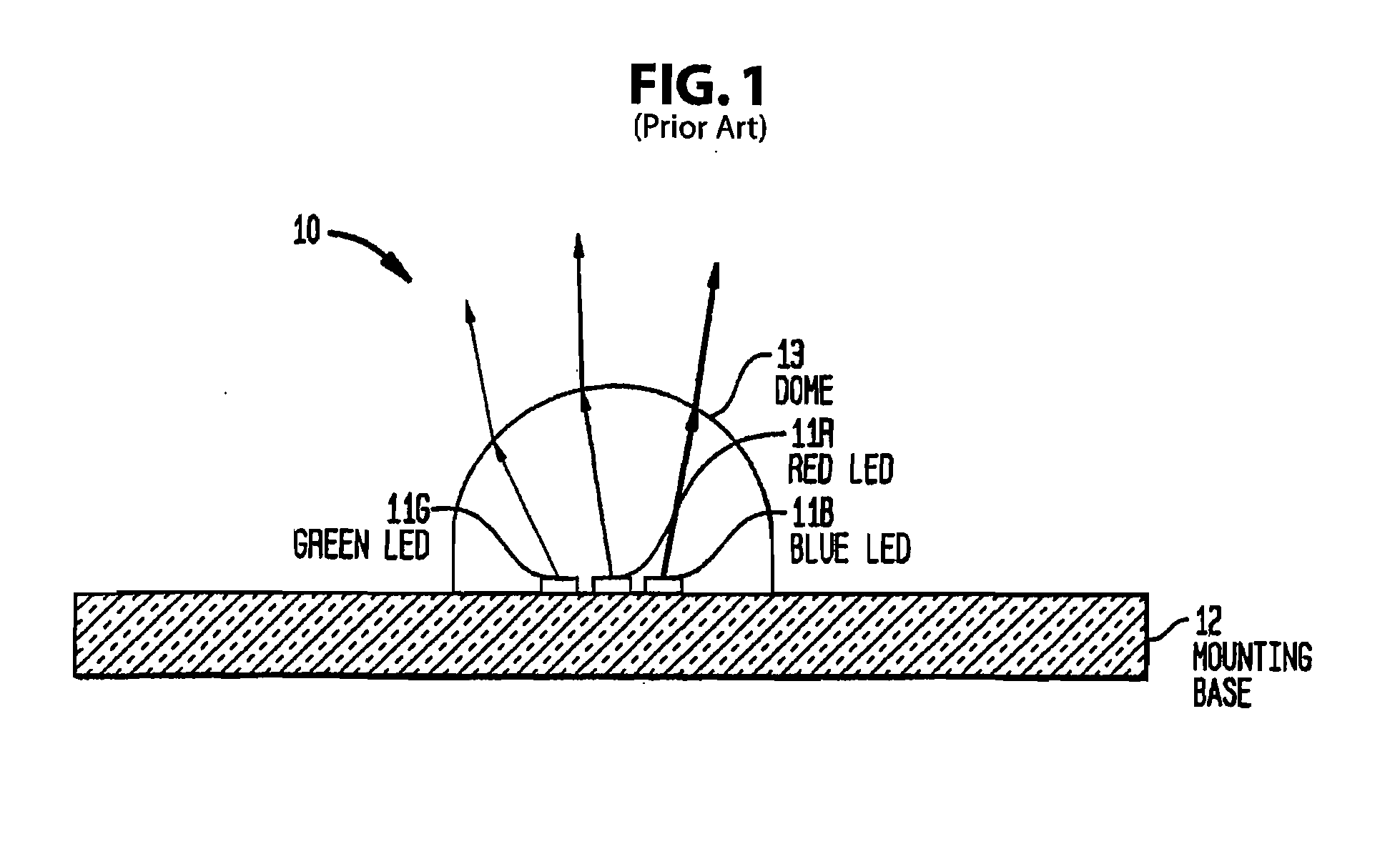
Unfortunately, conventional multi-colored LEDs, including conventional RGB assemblies, suffer from poor color mixing.
All such secondary optic devices suffer from several disadvantages.
External devices may be bulky and unwieldy for integrated luminaire applications.
This is undesirable for high intensity narrow distribution applications.
TIR or mirror integrators may bring some or all of the luminous intensity back to a full overlap at a given distance from the illumination sources, but suffer from poor matching at other distances from the source.

Method used


Image

  • Optical devices for controlled color mixing
  • Optical devices for controlled color mixing
  • Optical devices for controlled color mixing

Examples


Embodiment Construction

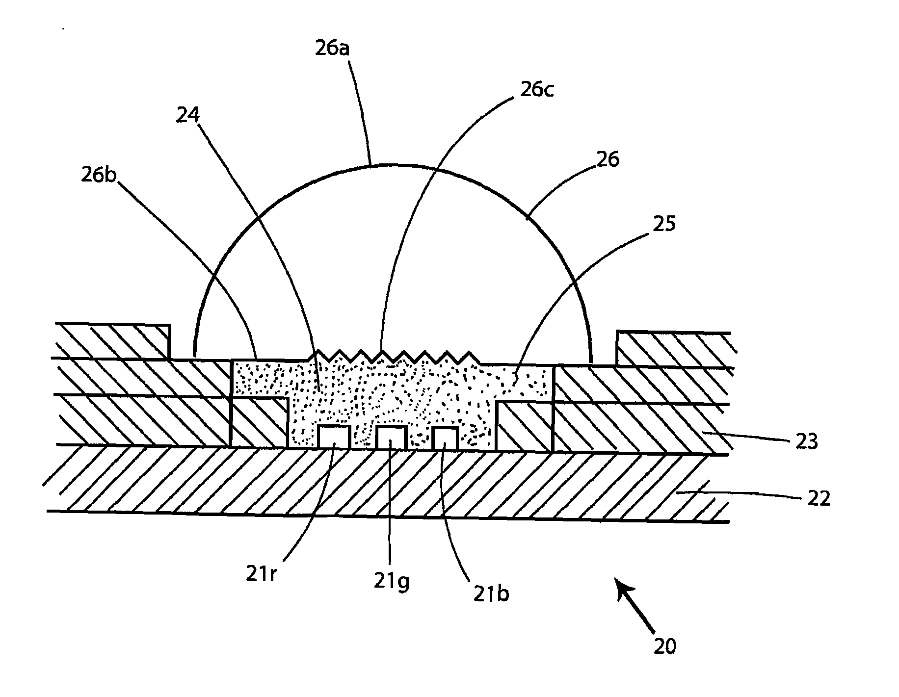
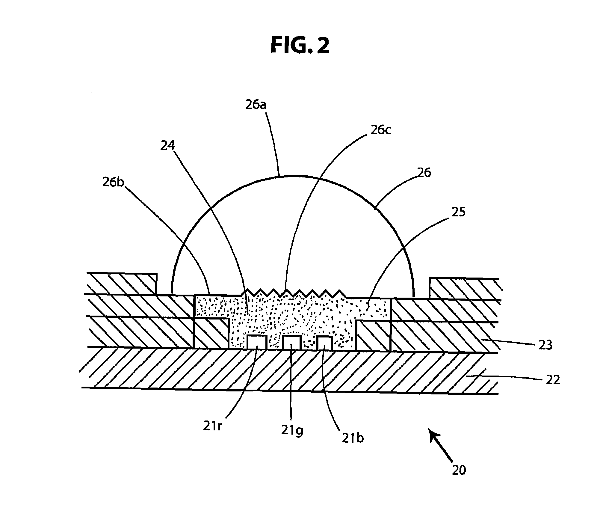
[0077] Referring to FIG. 2, there is shown a schematic cross-section of a multicolor LED assembly 20, according to an embodiment of the present invention. The assembly 20 includes different color LEDs (e.g. 21R, 21B, 21G) that are packaged and configured for enhanced mixing of the light emitted from different color LEDs. The assembly 20 includes a mounting substrate 22 preferably made of metal, one or more overlying layers 23 preferably made of ceramic with an opening defining a surface cavity 24. A plurality of the LED die 21R, 21G, 21B are mounted in the cavity 24 and in thermal contact with the substrate 22. The LED die 21 can preferably be in direct contract with substrate 22 as shown in FIG. 2. Optionally, the LED die 21 can be in thermal contact with the substrate 22 through an intervening thermal-conductive layer (not shown) which preferably matches the coefficient of thermal expansion of the LED die 21, to minimize stress on the die due to expansion or contraction at a rate ...


PUM


Abstract

The present invention provides a multicolor LED assembly packaged with improved and controlled color mixing to create a more uniform color mixture. The assembly includes at least one lens overlying an encapsulant which encapsulates a plurality of LED dies. The lens includes a top surface and a bottom surface with the contour of the bottom surface designed to redirect light from each of the LED dies in different directions towards the top surface of the lens. The contoured shaped of the bottom surface of the lens redirects light from each of the plurality of LED dies such that illuminance and luminous intensity distributions of the plurality of LED dies substantially overlap, wherein the deviation from complete overlap is less than a predetermined amount which is substantially imperceptible to the average human eye.

Description

[0001] This application claims priority to provisional U.S. application No. 60 / 792,885 filed Apr. 18, 2006 under 35 U.S.C. § 111(b), the contents of which are incorporated herein by reference.[0002] Numerous references including various publications are cited and discussed in the description of this invention. The citation and / or discussion of such references is provided merely to clarify the description of the present invention and is not an admission that any such reference is “prior art” to the present invention. All references cited and discussed in this specification are incorporated herein by reference in their entirety and to the same extent as if each reference was individually incorporated by reference. FIELD OF THE INVENTION [0003] The present invention relates to optical devices, more specifically, the present invention relates to multicolor optical light source assemblies with controlled color mixing for a uniform color mixture. BACKGROUND OF THE INVENTION [0004] Light e...

Claims


Application Information

Patent Timeline
IPC IPC(8): F21V9/00H01L33/54H01L33/58
CPCG02B27/0955H01L25/0753H01L33/54H01L33/58G02B19/0014F21V9/00G02B19/0066G02B19/0028H01L2933/0091H01L2924/0002H01L2924/00
Inventor BAILEY, EDWARDHARRAH, SHANE
Owner LIGHTING SCI GROUP
Learn More