
Image pickup device and image pickup apparatus

a pickup device and image technology, applied in the field of image pickup devices and image pickup apparatuses, can solve the problems of erroneous determination, significant labor to set the threshold value for each pixel, and inability to achieve the tone reproduction in the high-intensity area

Active Publication Date: 2007-11-22
ADVANCED INTERCONNECT SYST LTD
View PDF2 Cites 33 Cited by
  • Summary
  • Abstract
  • Description
  • Claims
  • Application Information

AI Technical Summary

Benefits of technology

[0037]Therefore, since the arithmetic processing for subtracting the luminance value indicated by the pixel data immediately after the reset (operation to empty accumulated electric charges of pixels) from the luminance values indicated by the non-standard exposure pixel data read out by the second reader may be performed, the fixed pattern noise generated by the variations in the individual characteristics of the respective photoelectric conversion elements (pixels) which constitute the photoelectric conversion unit may be eliminated from the non-standard exposure pixel data. In other words, in the nondestructive read-out method, since much noise are mixed to the non-standard exposure pixel data including the read out electric charges, the noise components mixed in the non-standard exposure pixel data may be eliminated by performing the differential arithmetic processing. Therefore, there is an advantage such that the prediction of the saturation / desaturation is achieved on the basis of the non-standard exposure pixel data of a luminance level with higher degree of accuracy. Moreover, since the wide dynamic range image data (HDR image data) may be generated using the non-standard exposure pixel data of the luminance level with a high degree of accuracy, there is an advantage such that the image quality of the wide dynamic range image is improved.
[0043]In this configuration, when there is not the non-standard exposure pixel data exposed during the exposure time shorter than the short exposure time corresponding to the selected non-standard exposure pixel data, the selected non-standard exposure pixel data and the standard exposure pixel data corresponding thereto may be used in the correction of the luminance level. Therefore, for example, the noise at the time of the increase correction may be reduced by performing the processing to add the non-standard exposure pixel data and the standard exposure pixel data. When there is the non-standard exposure pixel data exposed for the exposure time shorter than the short exposure time corresponding to the selected non-standard exposure pixel data, in the correction of the luminance level, the selected non-standard exposure pixel data, and the non-standard pixel data and the standard exposure pixel data exposed for the short exposure time corresponding thereto may be used. Therefore, for example, by performing the processing for adding the two types data, that is, the non-standard exposure pixel data and the standard exposure pixel data having different exposure times, the noise at the time of the increase correction may be reduced.
[0047]In this configuration, the processing to add the result obtained by multiplying the value obtained by subtracting the first saturation prediction luminance value from the first non-standard exposure pixel data by the first normalization coefficient and the luminance value of the standard exposure pixel data may be performed in the correction of the luminance level of the first non-standard exposure pixel data when there is not the second non-standard exposure pixel data as the non-standard exposure pixel data exposed for a short exposure time shorter than the short exposure time corresponding to the first non-standard exposure pixel data as the selected non-standard exposure pixel data, so that the noise at the time of the increase correction by the adding process is achieved. In other words, the amount of noise amplified at the time of multiplication is reduced in comparison with multiplying the luminance value of the first non-standard exposure pixel data simply by the first normalization coefficient, and the noise can further be reduced for performing the addition process with respect to the standard exposure pixel data.
[0048]Since the generation of the HDR image data using such first non-standard exposure pixel data with the noise reduced, there is an advantage such that the wide dynamic range image in which the image quality is stabilized in comparison with the related art is acquired.
[0053]In this configuration, when there is the second non-standard exposure pixel data as the non-standard exposure pixel data exposed for the exposure time shorter than the short exposure time corresponding to the first non-standard exposure pixel data as the selected non-standard exposure pixel data, in the correction of the luminance level of the first non-standard exposure pixel data, the process of adding the result obtained by multiplying the value obtained by subtracting the second saturation prediction luminance value from the second non-standard exposure pixel data by the second normalization coefficient and the luminance value indicated by the first standard exposure pixel data, and adding the result of multiplication obtained by multiplying the result of addition by the first normalization coefficient and the luminance value of the standard exposure pixel data may be performed. In other words, the amount of noise amplified at the time of multiplication is reduced more than multiplying the luminance value of the first non-standard exposure pixel data simply by the first normalization coefficient, and the adding process of the second non-standard normalization exposure pixel data and the standard exposure pixel data is also performed. Therefore the noise may further be reduced.

Problems solved by technology

More specifically, the image pickup device includes more dark current noise with elapse of time and subjects to more influence of the noise.
Variations in sensitivity or saturation from pixel to pixel also result in erroneous determination.
Although this problem may be solved by changing the threshold value according to variations in characteristics of the respective pixels, a significant labor to set the threshold value for each pixel is required.
Since the Knee system includes level compression of a high-intensity area, there arises a problem such that tone reproduction in the high-intensity area is impaired and linearity is disappeared in the device which can display a wide dynamic range (for example, the device which has a capability of contrast display of, for example, 10000:1), so that reproduction of the real colors are not achieved (in the case of a sensor in which a color filter is mounted).
As another problem, when the standard exposed image and the non-standard exposed image are taken at separate timings twice and are combined, a blurred image is resulted.
Such noise may cause the degradation of the image quality as a matter of course.

Method used


Image

  • Image pickup device and image pickup apparatus
  • Image pickup device and image pickup apparatus
  • Image pickup device and image pickup apparatus

Examples


first embodiment

[0090]Referring now to the drawings, an image pickup device, an image pickup apparatus, an image pickup system, and an image pickup method according a first embodiment will be described. FIG. 1 to FIG. 13 are drawings showing the image pickup device, the image pickup apparatus, the image pickup system, and the image pickup method according to the embodiments of the invention.

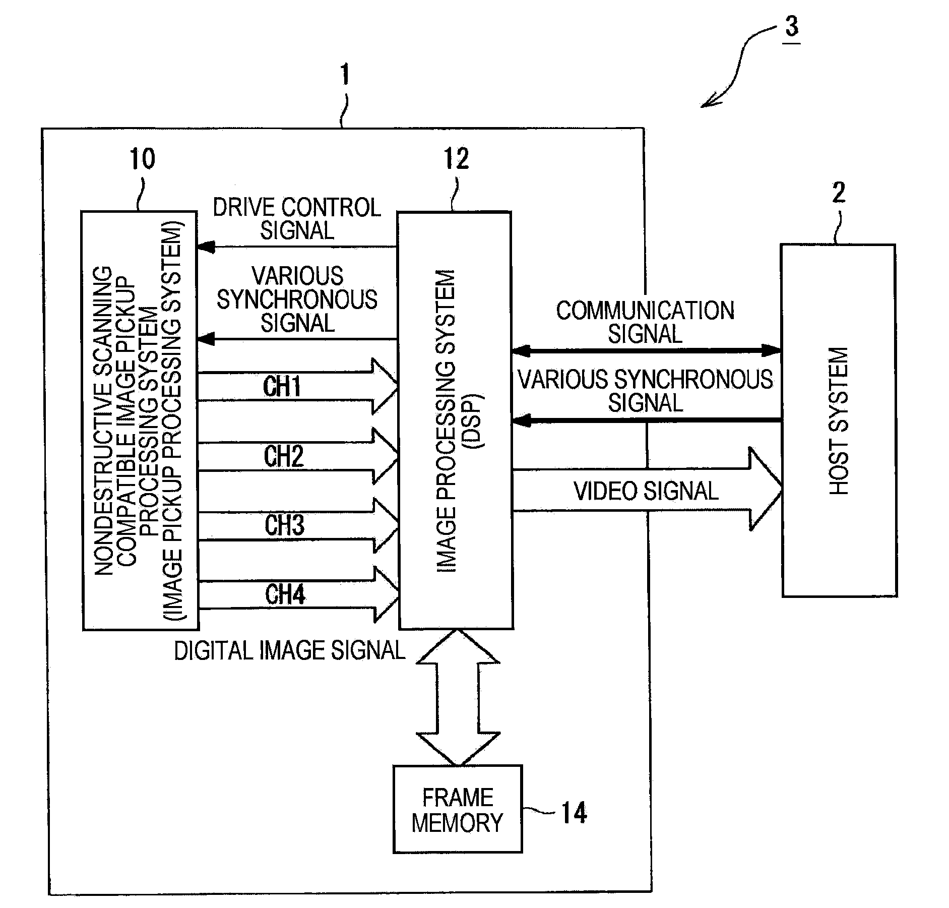
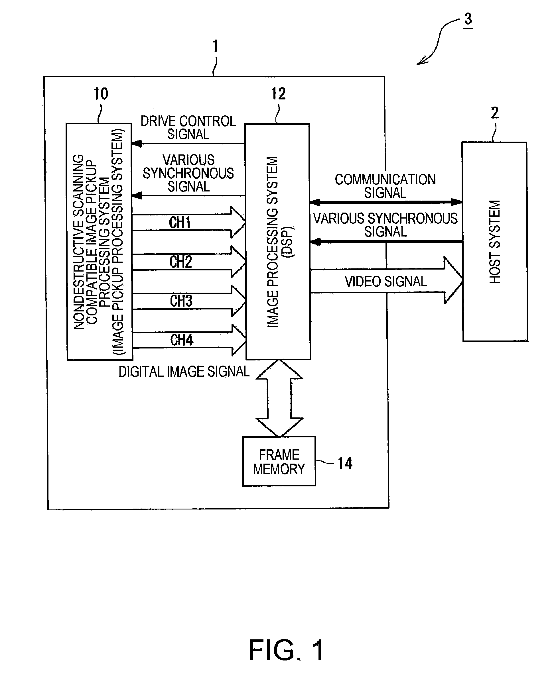
[0091]On the basis of FIG. 1, a schematic configuration of an image pickup apparatus 1 according to the embodiment of the invention will be described. FIG. 1 is a block diagram showing a schematic configuration of an image pickup system 3 according to the embodiment of the present invention.

[0092]The image pickup system 3 includes the image pickup apparatus 1 and a host system 2 as shown in FIG. 1.

[0093]The image pickup apparatus 1 includes a nondestructive scanning compatible image pickup processing system 10 (hereinafter referred to as “image pickup processing system 10”) which reads out pixel signals from lin...

second embodiment

[0198]Referring now to the drawings, the image pickup device, the image pickup apparatus, the image pickup system, and the image pickup method according to a second embodiment of the invention will be described. FIGS. 14A and 14B show the image pickup device, the image pickup apparatus, the image pickup system, and the image pickup method according to the second embodiment of the invention.

[0199]The second embodiment is different from the first embodiment in that both of the super-short exposure pixel data and the short exposure pixel data are acquired as the non-standard pixel data and the saturation / desaturation is predicted on the basis of the super-short exposure pixel data and the short exposure pixel data and, when it is predicted that the target pixel will be saturated in the short exposure time T1, the combined output (HDR pixel data) is generated using all of the super-short exposure pixel data, the short exposure pixel data, and the standard exposure pixel data. Therefore,...


PUM


Abstract

An image pickup device having a photoelectric conversion unit having a plurality of photoelectric conversion elements arranged in a matrix pattern for converting exposed light into electric charges and accumulating the same and an electronic shutter function for controlling the exposure time for each frame including: a first reader for reading out electric charges exposed during a standard exposure time from respective pixels including the photoelectric conversion elements in the exposed area of the photoelectric conversion unit in a destructive read-out method; a second reader for reading out electric charges exposed during a short exposure time, which is an exposure time shorter than the standard exposure time, from the respective pixels including the photoelectric conversion elements during the same exposure period as the first reader in a nondestructive read-out method; and a saturation predictor for predicting whether or not the amounts of accumulated electric charges in the respective pixels being exposed during the standard exposure time are saturated on the basis of a non-standard exposure pixel data including the electric charges being exposed during the short exposure time, which are read out by the second reader.

Description

BACKGROUND[0001]1. Technical Field[0002]The present invention relates to an image pickup device and an image pickup apparatus which can read out electric charges from a photoelectric conversion element in a destructive read-out method and a nondestructive read-out method.[0003]2. Related Art[0004]As one of problems of an image pickup apparatus using a solid-state image pickup device represented by a digital still camera, narrowness of the dynamic range is exemplified. Therefore, an image acquired by photographing a scene having a significantly large contrast includes an over exposure (saturation of pixels) in a high-intensity area and blackened display in a low-intensity area.[0005]A number of methods are proposed in order to solve the above-described problem. As one of these methods, there is a method of combining two (or a plurality of) images having different exposure values. Known examples in which this method is employed include an image pickup apparatus described in JP-A-2004-...

Claims


Application Information

Patent Timeline
Patent Type & Authority Applications(United States)
IPC IPC(8): H04N5/235G03B7/08H04N23/76H04N25/00
CPCH04N5/2353H04N5/35581H04N5/35554H04N5/2355H04N23/73H04N23/741H04N25/583H04N25/589
Inventor KURANE, HARUHISA
Owner ADVANCED INTERCONNECT SYST LTD
Learn More