Adjustable on-chip sub-capacitor design

a sub-capacitor and design technology, applied in the field of capacitors, can solve the problems of inability to accurately predict the value of an on-chip capacitor, differences of 10% or more between high and low capacitor values, and no known procedure for adjusting or tuning the capacitance value of a capacitor

Active Publication Date: 2007-11-22
GLOBALFOUNDRIES US INC
View PDF7 Cites 11 Cited by
  • Summary
  • Abstract
  • Description
  • Claims
  • Application Information

AI Technical Summary

Problems solved by technology

One of the drawbacks in present on-chip capacitor designs is the inability to accurately predict the value of an on-chip capacitor.
In fact, an error of 5% or more in the design value of the capacitor is common, resulting in differences of 10% or more between high and low capacitor values.
Unfortunately, there is no known procedure to adjust or tune the capacitance value of a capacitor after its manufacture.
The need for accuracy results in high rejection rates and decreased yields in chip production.

Method used


Image

  • Adjustable on-chip sub-capacitor design
  • Adjustable on-chip sub-capacitor design
  • Adjustable on-chip sub-capacitor design

Examples


Embodiment Construction

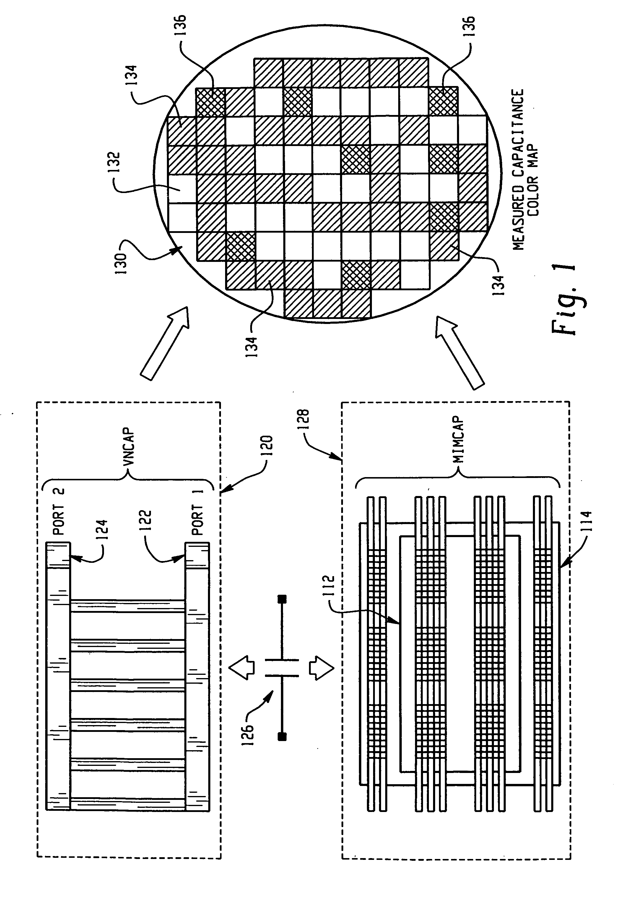
[0031]FIG. 1 shows the current state of the art on-chip capacitors VNCAP (120) and MIMCAP (128) and a measured capacitance color map. The VNCAP (120) has two vertical capacitor ports, PORT 1 (122) and PORT 2 (124) and consists of alternating parallel conductive plates and insulators to generate capacitance. The MIMCAP (128) also has two ports which are top plate (112) and bottom plate (114) and has an insulator (or dielectric) between two plates. These on-chip capacitors can be more simply shown by the capacitor symbol (126). The on-chip capacitors can present huge variations (>±10%) from target values when measured as shown in FIG. 1 (E).

[0032]The capacitance map shows how much the capacitance value of on-chip capacitors can vary. This example shows a 300 mm wafer (130) that includes 77 sites with different patterns to represent variations from a targeted capacitance. The sites (132) with no cross hatching represent the highest capacitance value. The sites (134) with a single cross...


PUM


Abstract

One or more on-chip VNCAP or MIMCAP capacitors utilize a variable MOS capacitor to improve the uniform capacitance value of the capacitors. This permits the production of silicon semiconductor chips on which are mounted capacitors having capacitive values that are precisely adjusted to be within a range of between about 1% and 5% of their design value. This optimization can be achieved by the use of a back-to-back connection between a pair of the variable MOS capacitors for DC decoupling. It involves the parallelization of on-chip BEOL capacitance of VNCAP and/or MIMCAP capacitors by the insertion in the FEOL of pairs of back-to-back variable MOS capacitors.

Description

FIELD OF THE INVENTION[0001]This invention relates to capacitors on semiconductor chips. More particularly, the invention relates to silicon semiconductor chips on which are mounted capacitors having capacitive values that are precisely calibrated within a range of between about 1% and 5% of their target values.BACKGROUND OF THE INVENTION[0002]To enhance the understanding of the discussion that follows, the abbreviations and terms listed below will have the definitions as shown.[0003]ADC—Analog to digital converter[0004]BEOL—Back end of line[0005]CA—Tungsten contact between metal and polysilicon[0006]Csub—Adjustable capacitor[0007]DAC—Digital to analog converter[0008]FEOL—Front end of line[0009]MIMCAP—Metal-insulator—metal capacitor[0010]MOS—Metal oxide silicon[0011]RF—Radio frequency[0012]VNCAP—Vertical native capacitor[0013]On-chip capacitors are critical components of integrated circuits that are fabricated on silicon semiconductors. These capacitors are used for a variety of pur...

Claims


Application Information

Patent Timeline
Patent Type & Authority Applications(United States)
IPC IPC(8): H01L27/108H01L29/94H01L29/76H01L31/119
CPCH01L23/5223H01L27/0688H01L27/0805H01L27/0808H01L2924/0002H01L2924/00
Inventor KIM, JONGHAEKIM, MOON J.PLOUCHART, JEAN-OLIVIERTRZCINSKI, ROBERT E.
Owner GLOBALFOUNDRIES US INC
Why Eureka
Try Eureka