Chock release column for use with expansible hole anchor

Inactive Publication Date: 2007-11-22
SIGMA IND
View PDF10 Cites 0 Cited by
  • Summary
  • Abstract
  • Description
  • Claims
  • Application Information

AI Technical Summary

Benefits of technology

[0010] The present invention is designed to overcome the deficiencies and shortcomings of the devices described above. The present invention is designed to reduce the manufacturing costs and the complexity of assembly. In all exemplary embodiments, the present invention relates to an improved expansible hole anchor with a chock releasing column which is advantageously secured about a load cable of the hole anchor and is operable for transmitting force to a center chock of the hole anchor, thereby dislodging the anchor from a hole. In all exemplary embodiments, the present invention advantageously provides an improved hole anchor which decreases side load forces which may be applied to the center chock during use through the use of an improved chock release column. The present invention is easily installed and removed from a hole formed with a solid structure. In one application, the present invention discloses a chock release column for use with a conventional hole anchor that is inserted into a hole drilled in a concrete wall at a construction site. A safety harness, lifeline, and other fall protection gear is secured to the worker and to the anchor to arrest the worker in the event of a fall. In another application, the present invention is directed to a chock release column for use with a conventional hole anchor that is applicable for use in securing equipment, such as scaffolding, to a concrete structure, or as a lift connection point for items with a suitable hole, such as preformed concrete or boulders, or for use in recreational rock climbing.
[0011] According to an exemplary embodiment, a chock release column is provided for use with a conventional, expansible anchor that is adapted for insertion into a hole formed with a structure provided. The hole anchor generally includes a load cable, a center chock attached to an end of said load cable, at least one, but preferably two, side chocks adjacent to said center chock and adapted for movement between an anchor-contracting position and an anchor-expanding position, whereby in said anchor-contracting position, said anchor is readily inserted into and removed from the hole of the structure, and in said anchor-expanding position, said anchor is locked inside the hole of the structure, and a chock release column secured about the load cable. In exemplary embodiments, the chock release column generally includes an enlarged head adapted for locating outside of the hole, said enlarged head defining a striking surface adapted for receiving a sudden force and transferring the force through said chock-release column to said center chock or at least one side chock, such that said at least one side chock is movable from the anchor-expanding position to the anchor-contracting position to thereby dislodge said anchor from the hole of the structure.

Problems solved by technology

However, substantial drawbacks and limitations exist in conventional expansible hole anchors.
In many cases, the anchor is so tightly lodged inside the hole that movement of the handle is difficult, if not impossible.
In practice, this procedure is generally ineffective; often resulting in mangled or broken retraction cables, and rendering the anchor unsuitable for future use.
This procedure further inconveniences the user by requiring the availability of special tools in order to access and release the anchor chocks.
A further problem of conventional anchors relates to the exposure of control cables operable for moving the anchor from the expanded condition to the contracted condition.
Typically, these cables will bear directly against an inside wall of the anchor hole, resulting in substantial abrasion and chaffing when the anchor is inserted into and removed from the hole.
Further wear is created when the worker moves about causing the control cables to grind against the concrete lip of the hole.
If left undetected, the worn cables will eventually foul the cable motion and cause the anchor to fail which may result in inoperability, serious injury, or death.
A further problem with conventional hole anchors is the number of components required for assembly and use.
Existing hole anchors require a large number of parts which disadvantageously increase the complexity and cost of manufacture.
In addition, conventional hole anchors disadvantageously have a striker head which may lose contact with the center chock, thus providing a defective unit.

Method used


Image

  • Chock release column for use with expansible hole anchor
  • Chock release column for use with expansible hole anchor
  • Chock release column for use with expansible hole anchor

Examples


Embodiment Construction

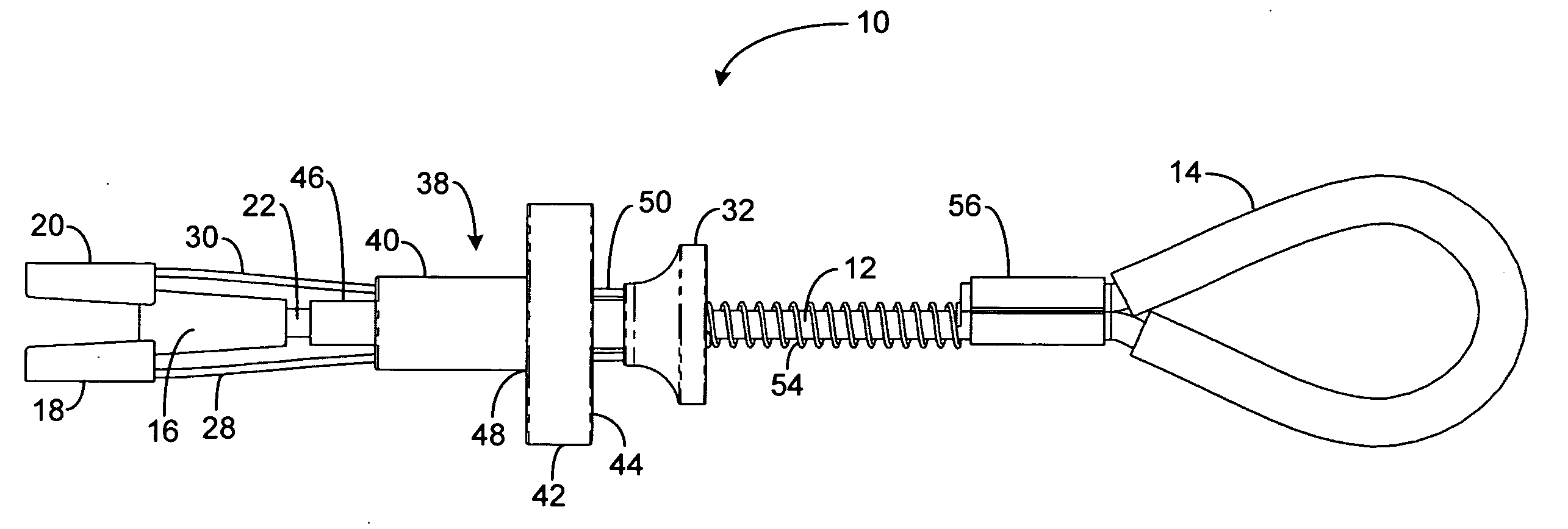
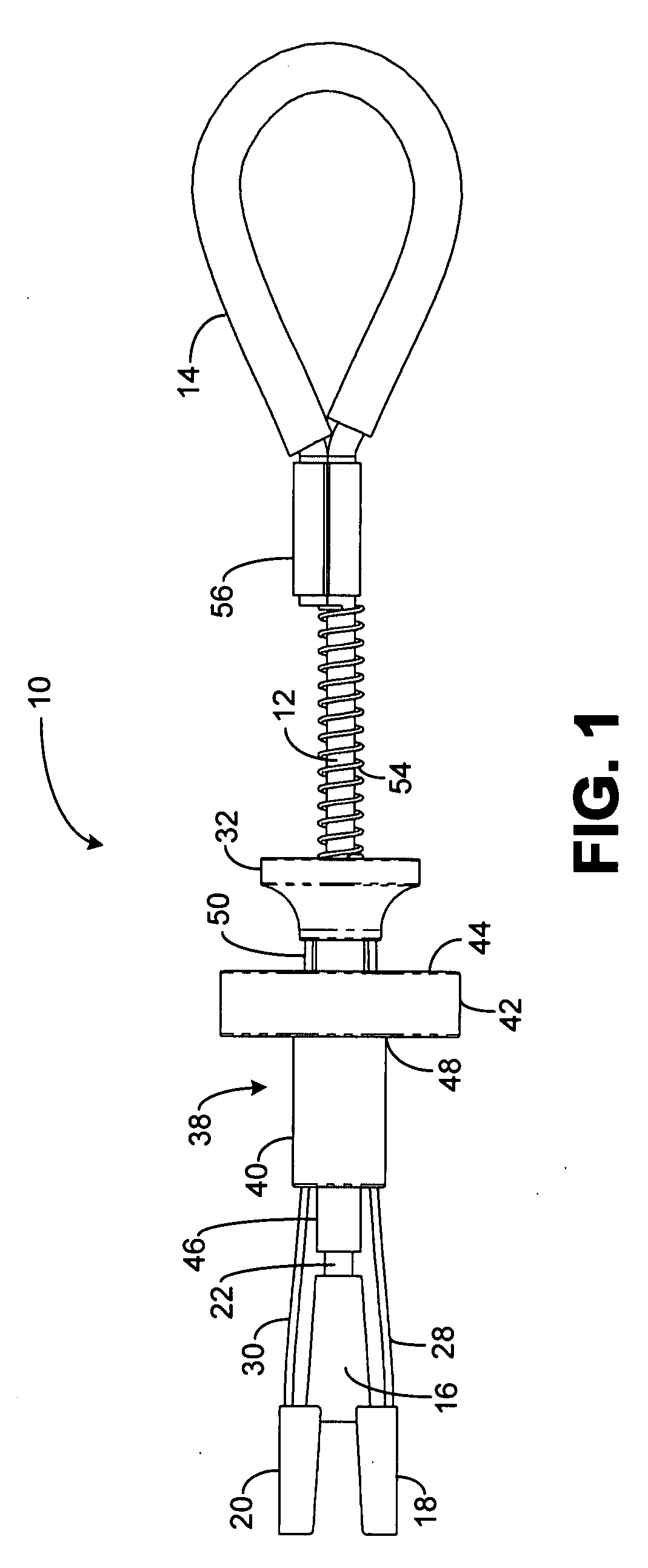
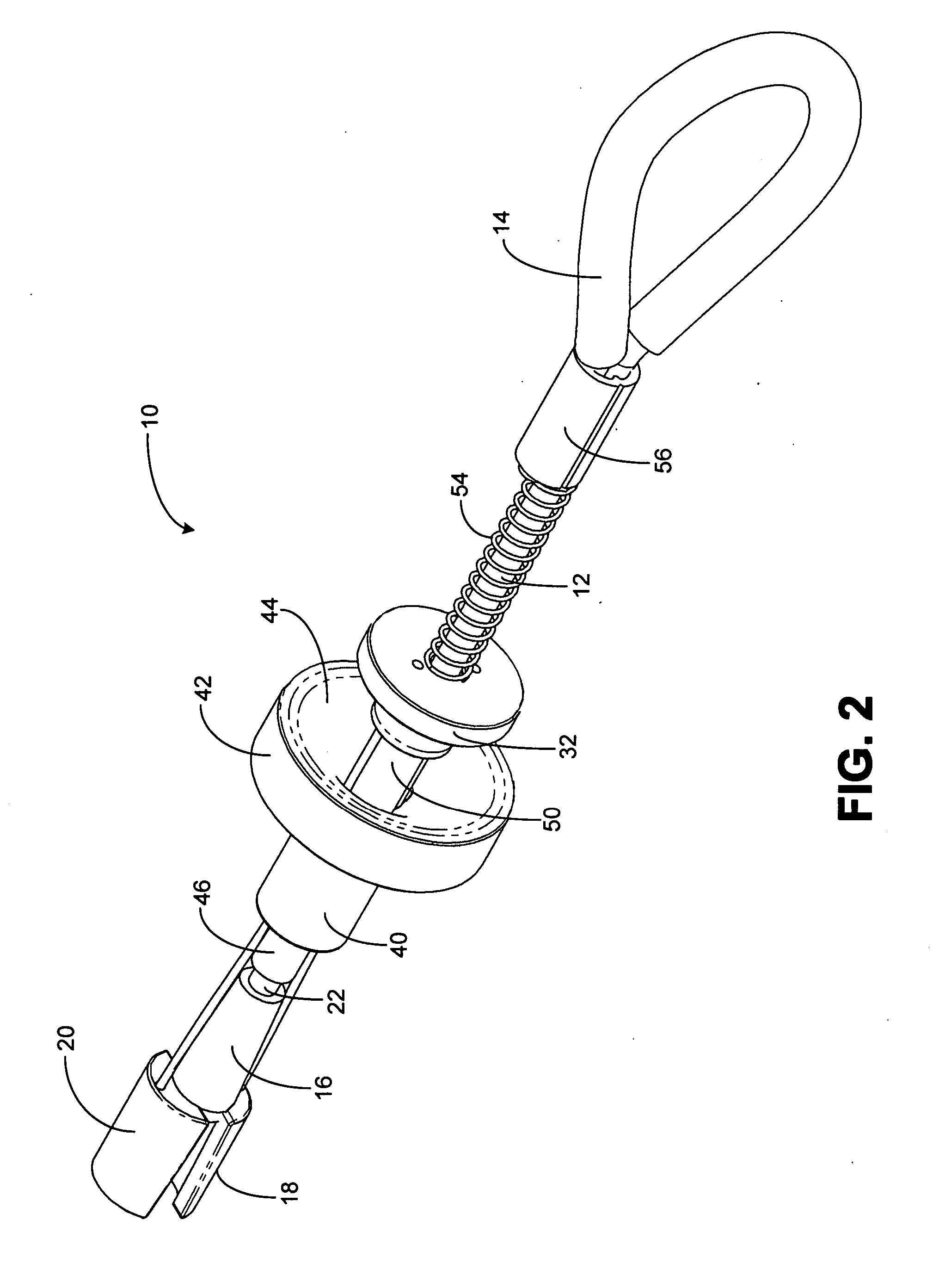
[0022] The present invention will now be described more fully hereinafter with reference to the accompanying drawings in which exemplary embodiments of the invention are shown. However, this invention may be embodied in many different forms and should not be construed as limited to the embodiments set forth herein. These exemplary embodiments are provided so that this disclosure will be both thorough and complete, and will fully convey the scope of the invention to those skilled in the art. Like reference numbers refer to like elements throughout the various drawings. Further, as used in the description herein and throughout the claims that follow, the meaning of “a”, “an”, and “the” includes plural reference unless the context clearly dictates otherwise. Also, as used in the description herein and throughout the claims that follow, the meaning of “in” includes “in” and “on” unless the context clearly dictates otherwise.

[0023] The present invention overcomes the shortcomings of con...


PUM


Abstract

A chock release column operable for use with conventional hole anchor devices is provided and generally includes a cable cylinder operable for being secured about a load cable of an expansible hole anchor, a chock clearance portion extending from the cable cylinder that it corresponds in size and shape to an end of the center chock, and an enlarged head adapted for locating outside of a hole of a structure, the enlarged head generally defining a striking surface adapted for receiving a sudden force and transferring the force through the chock release column to a center chock or at least one side chock of the expansible hole anchor, such that the at least one side chock is movable from the anchor-expanding position to the anchor-contracting position to thereby dislodge said anchor from the hole of the structure.

Description

CROSS REFERENCE TO RELATED APPLICATION(S) [0001] This application is a continuation-in-part of U.S. patent application Ser. No. 11 / 069,646, filed on Mar. 1, 2005, and entitled “EXPANSIBLE HOLE ANCHOR WITH ENLARGED CHOCK-RELEASING STRIKER HEAD,” which is a continuation of and claims the benefit of priority of PCT / US04 / 24129, filed on Jul. 27, 2004, the content of all the aforesaid applications are relied upon and incorporated by reference in its entirety.BACKGROUND OF THE INVENTION [0002] 1. Field of the Invention [0003] The present invention relates generally to safety devices and methods for fall protection, and more specifically, to safety devices including, in an exemplary embodiment, a chock release column operable for use with conventional expansible hole anchors. [0004] 2. Technical Background [0005] In the construction industry, it is often necessary to provide fall protection for workers or objects suspended at heights. Conventionally, expansible hole anchor bolts are used t...

Claims


Application Information

Patent Timeline
IPC IPC(8): E04G21/32
CPCA62B35/0068E04G21/3261A63B29/024E04G21/3276
Inventor REEVES, ERIC WILLIAM
Owner SIGMA IND
Why Eureka
Try Eureka