
Heat sink of plasma display apparatus

a plasma display and heat sink technology, applied in the direction of instruments, cooling/ventilation/heating modifications, identification means, etc., can solve the problems of troublesome manufacturing process, troublesome manufacturing time and operation procedure, etc., and achieve the effect of facilitating processing, reducing manufacturing costs, and improving productivity

Inactive Publication Date: 2007-11-22
LG ELECTRONICS INC
View PDF6 Cites 66 Cited by
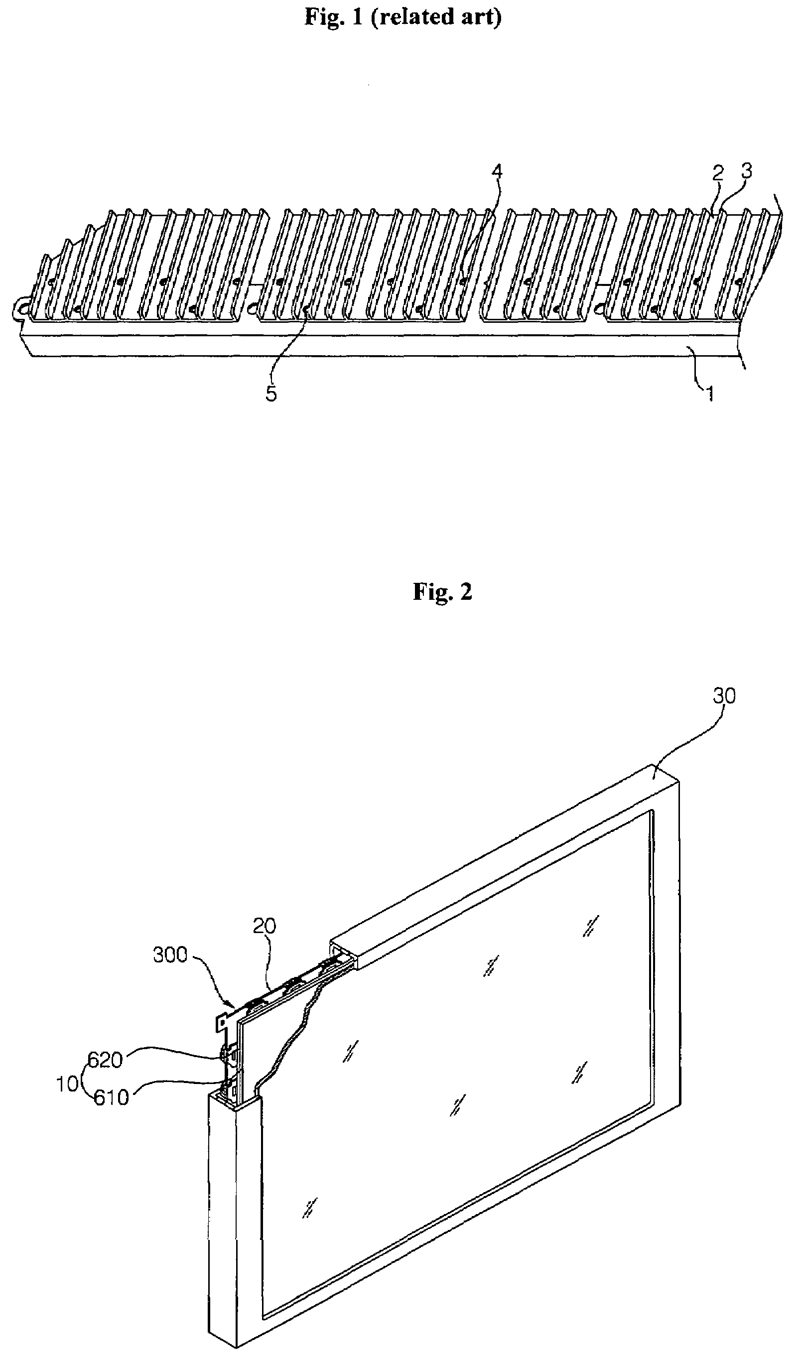
  • Summary
  • Abstract
  • Description
  • Claims
  • Application Information

AI Technical Summary

Benefits of technology

[0016]The objective of the present invention is to provide a heat sink of a plasma display apparatus and manufacturing method of the same, wherein the manufacturing process of which is simple through an extruding process.
[0018]Further, another object of the present invention is to provide a heat sink of the plasma display apparatus and manufacturing method of the same, which is capable of preventing from being twisted or bended when it is extruded.
[0033]As described in the above, as to the heat sink of the plasma display apparatus according to the present invention and manufacturing method of the same, there is an effect that a processing is facilitated because the widthwise air channel and the lengthwise air channel are formed with a extruding processing and a rolling processing. In addition, as the extruding processing and the rolling processing are consecutively performed, the productivity is much more improved in comparision with a conventional method.
[0034]Further, as to the heat sink of the plasma display apparatus according to the present invention and manufacturing method of the same, there is an effect that the cost of manufacture the extrusion die is much more inexpensive in comparision with a diecasting or the other press processing because the heat sink is processed through the extruding by the extrusion die. In addition, the damage of the extrusion die in manufacturing is remarkably less to implement a high durability.
[0035]Further, as to the heat sink of the plasma display apparatus according to the present invention, bending or transforming into one side is prevented in the extrusion die when being extruded because the both ends of the heat sink are manufactured as a pair heat sink form in which the both ends of the heat sink are symmetrical.

Problems solved by technology

However, there is a problem that the manufacturing time and the operation procedure is troublesome because each component is combined through an additional assembly process.
Therefore, there is a problem in that the manufacturing process is complicated.

Method used


Image

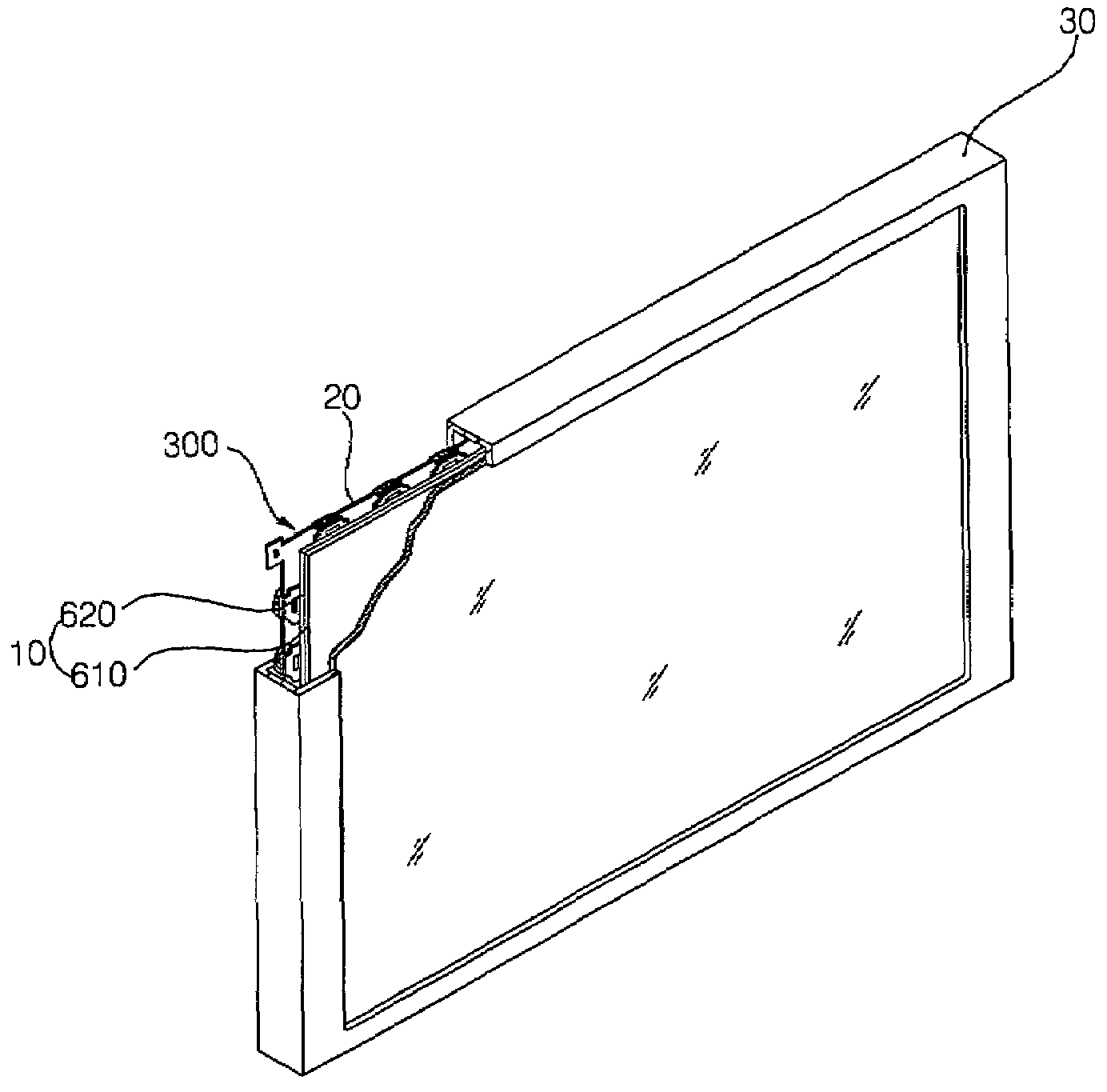
  • Heat sink of plasma display apparatus
  • Heat sink of plasma display apparatus
  • Heat sink of plasma display apparatus

Examples


second embodiment

[0119]FIG. 12 is a side view in which a heat sink manufacturing apparatus according to the present invention is illustrated.

[0120]As to the second embodiment according to the present invention, it is identical with the first embodiment except that the star roller is comprised as miltiple form in the first embodiment.

[0121]That is, in the star roller 520 of a first row which performs first rolling with the extruded product 401 extruded from the extrusion die 410, only the tooth form 422 is formed without the addition tooth 424 unlike the first embodiment. At the same time, the tooth form 422 is formed with the addition tooth form 424 like the first embodiment in the star roller 420 of the second row.

[0122]Therefore, the star roller 520 of the first row compresses the extruded product 401 to form only the lengthwise direction air channel 112, while the star roller 420 of the second row processes the platform 115 with a slow slope through the addition tooth form 424.

[0123]In addition, ...

first embodiment

[0149]FIG. 16 shows a timing diagram of a first embodiment on driving signals for driving a plasma display panel in one subfield divided as described in the above.

[0150]The subfield comprises a pre reset period for forming positive wall charges on the scan electrodes Y and forming negative wall charges on the sustain electrode Z, a reset period for initializing the discharge cells of the whole screen by using the wall charge distribution formed due to the pre reset period, an address period for selecting the discharge cell, and a sustain period for maintaining the discharge of the selected discharge cells.

[0151]The reset period is comprised of a set down period and a setup period. In the setup period, a ramp-up waveform is simultaneously applied to all the scan electrodes to generate a microdischarge in all the discharge cells. Accordingly, the wall charge is generated. In the setdown period, a ramp-down waveform descending from the positive polarity voltage lower than the peak volt...


PUM


Abstract

As to a heat sink manufacturing method of a plasma display apparatus according to the present invention and the manufacturing device, a widthwise direction air channel and a lengthwise direction air channel are formed through a extrusion and a rolling processing to facilitate a processing with a continuous extrusion and rolling processing. Accordingly, the productivity is notably improved.

Description

[0001]This application claims the benefit of Korean Patent Application No. 10-2006-0044866 filed on May 18, 2006, which is hereby incorporated by reference for all purposes as if fully set forth herein.BACKGROUND OF THE INVENTION[0002]1. Field of the Invention[0003]The present invention relates to the heat sink of a plasma display apparatus, in particular, to the heat sink of the plasma display apparatus having a low cost and a simple process through being manufactured with a extruding processing and a rolling processing.[0004]2. Description of the Background Art[0005]The plasma display apparatus PDP is a flat panel display apparatus which displays an image by using a plasma discharge, being used as a high definition television, a monitor, and an indoor / outdoor display for advertisement because it suitable for big screen with a fast response speed.[0006]FIG. 1 is a perspective drawing in which a conventional heat sink of a plasma display apparatus is illustrated.[0007]The convention...

Claims


Application Information

Patent Timeline
Patent Type & Authority Applications(United States)
IPC IPC(8): H05K7/20G09F9/00
CPCH05K7/20963H01J11/34H01J17/28
Inventor KIM, BOG RYONG
Owner LG ELECTRONICS INC
Learn More