Walking foot for sewing machine

a technology of walking foot and sewing machine, which is applied in the field of walking foot, can solve the problem that the pressing foot cannot be changed to a different one, and achieve the effect of improving the comfort of the patien

Active Publication Date: 2007-11-22
BROTHER KOGYO KK
View PDF11 Cites 11 Cited by
  • Summary
  • Abstract
  • Description
  • Claims
  • Application Information

AI Technical Summary

Benefits of technology

[0012]In the above-described construction, the presser foot can be disengaged from the engagement support portion of the support when at least one engagement support portion is just switched from the engagement position where the engagement supporting port...

Problems solved by technology

Since the side plates are fixed to the holder, there is a...

Method used


Image

  • Walking foot for sewing machine
  • Walking foot for sewing machine
  • Walking foot for sewing machine

Examples


Embodiment Construction

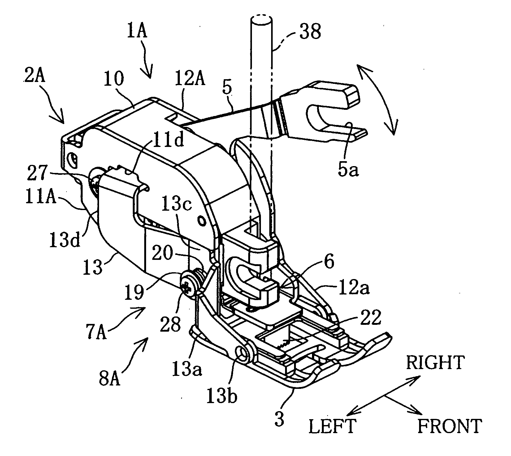
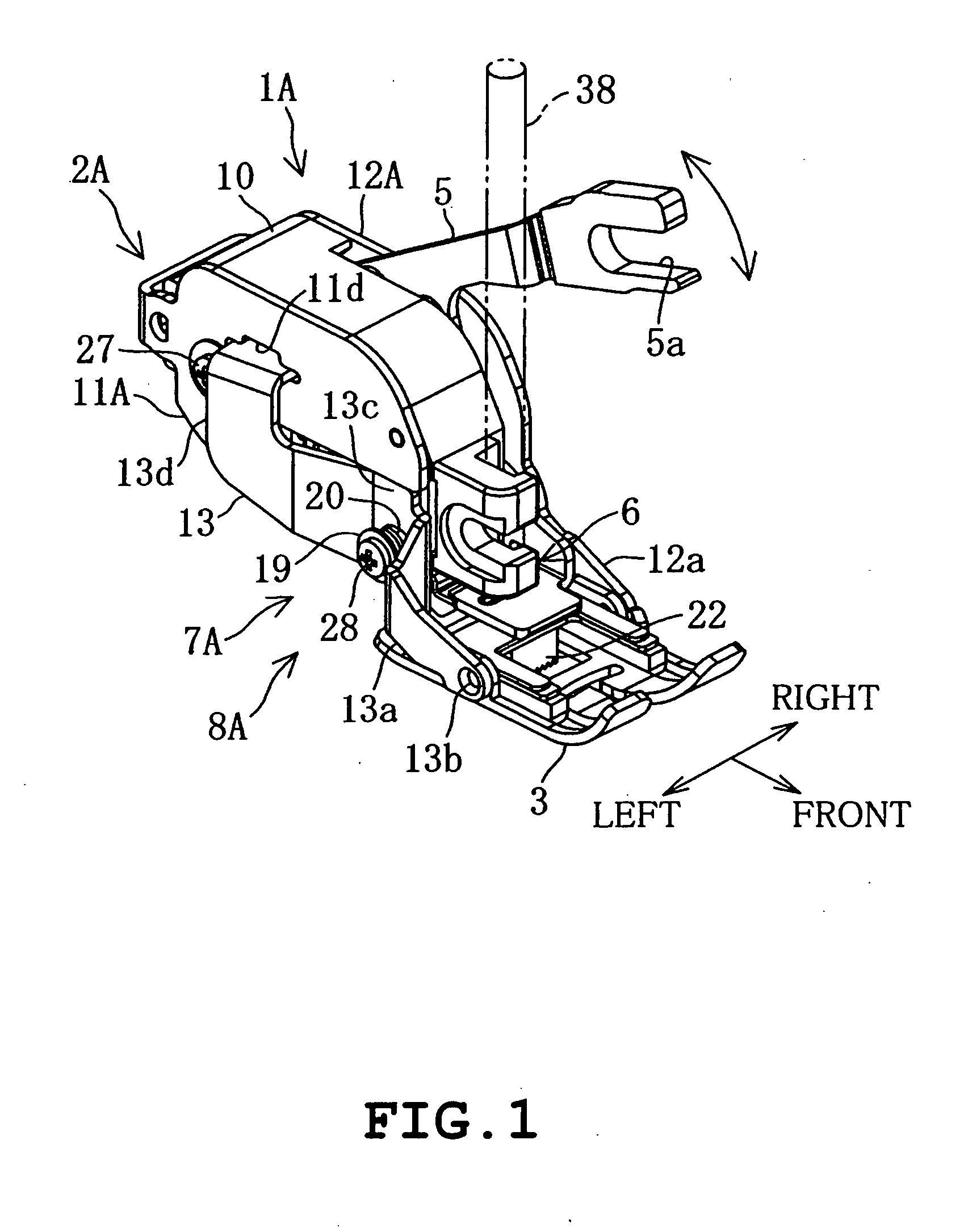
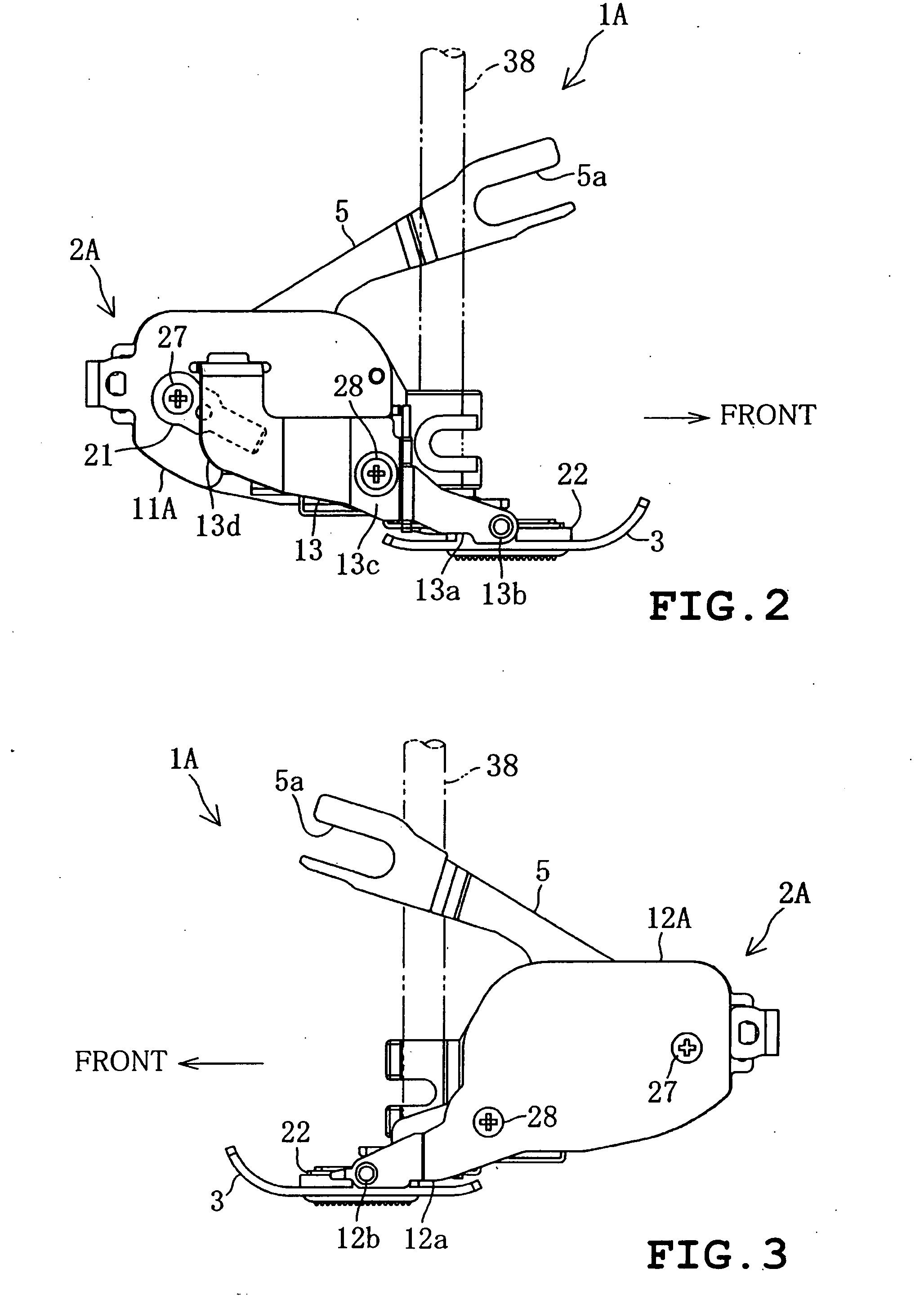
[0057]A first illustrative example of the present disclosure will be described with reference to FIGS. 1 to 7 and 40 to 43. Firstly, a sewing machine 30 to which a walking foot of the illustrative example is detachably attached. The sewing machine 30 includes a sewing bed 31, a pillar 32 extending upward from a right end of the bed 31, a sewing arm 33 extending leftward from an upper part of the pillar 32 and a head 34 provided on the left end side of the arm 33 as shown in FIG. 43. A needle plate 35 is mounted on an upper face of the bed 31. A sewing machine main shaft driven by a sewing machine motor is provided in the arm 34 although neither sewing machine main shaft nor sewing machine motor is shown. A needlebar 36 driven by the sewing machine main shaft is attached to the head 34 so as to be moved vertically. The needlebar 36 has a lower end to which a sewing needle 37 is attached. Furthermore, a presser bar 38 is attached to the head 34 so as to be raised and lowered. The pres...


PUM


Abstract

A walking foot for a sewing machine includes a presser foot having a pair of supported portions, an upper feed dog feeding workpiece cloth in synchronization with vertical movement of a needlebar, a supporting member fixed to a lower end of the presser bar and having a pair of engagement supporting portions supporting the presser foot, a swinging supporting mechanism engaging the engagement supporting portions with the supported portions from horizontally outside respectively so that the presser foot is supported on the supporting member so as to be swingable, and a disengaging mechanism moving at least one of the engagement supporting portions horizontally outward from an engagement position where the engagement supporting portion is in engagement with the supported portion of the presser foot, thereby being capable of switching the engagement supporting portion to a disengagement position where the engagement supporting portion is disengaged from the supported portion.

Description

CROSS-REFERENCE TO RELATED APPLICATIONS[0001]This application is based upon and claims the benefit of priority from the prior Japanese Patent Application No. 2006-141292 filed on May 22, 2006, the entire contents of which are incorporated herein by reference.BACKGROUND[0002]1. Technical Field[0003]The present disclosure relates to a walking foot which is attached to a lower end of a presser bar in a sewing machine so as to be located at an upper side of workpiece cloth, thereby feeding the workpiece cloth placed at an upper side of a needle plate in synchronization with a feed dog provided on a sewing bed.[0004]2. Description of the Related Art[0005]In quilting, two pieces of workpiece cloth are sewn so as to be combined together with cotton being stuffed therebetween using a sewing machine. In this case, an operator conventionally attaches a walking foot to a lower end of a presser bar of the sewing machine so that the upper workpiece cloth is fed by the walking foot in synchroniza...

Claims


Application Information

Patent Timeline
IPC IPC(8): D05B27/16
CPCD05B27/04D05B29/12D05B29/06
Inventor FUJIHARA, SHINYANIIZEKI, TOMOYASU
Owner BROTHER KOGYO KK
Why Eureka
Try Eureka