
Pedal Assembly Having a Safety Device

a technology of safety device and pedal assembly, which is applied in the direction of mechanical control device, controlling member, instruments, etc., can solve the problems of serious injury to the driver, total loss of the ability to manoeuvre the vehicle by the driver, and danger to the safety, so as to reduce the

Inactive Publication Date: 2007-11-22
DRIVESOL WORLDWIDE
View PDF9 Cites 23 Cited by
  • Summary
  • Abstract
  • Description
  • Claims
  • Application Information

AI Technical Summary

Benefits of technology

[0007] The object of the present invention is to realise a safety device for which there is provided a lock which is actively triggered in connection with a collision, but where there is subsequently an extreme point at which the pedal shaft is arrested so that an upper pivotal point for the pedal arm is obtained around which the pedal arm may move and continue to impart to the pedal the ability to act, possibly with a reduced effect.
[0008] The advantages inherent in the present invention are that a pedal support with low pedal penetration will be realised at the same time as the total safety of a motor car provided with the present safety device is increased in that the pedals retain at least a certain effect even after a collision.

Problems solved by technology

Since a large degree of pedal penetration may result in serious injury to the driver, attempts are made to render pedal penetration as slight as possible.
One drawback inherent in this solution is that the driver totally loses the ability to manoeuvre the vehicle with the aid of the pedals when the lock has been activated.
This may constitute a danger to safety that could even aggravate the consequences of a road accident.

Method used


Image

  • Pedal Assembly Having a Safety Device
  • Pedal Assembly Having a Safety Device
  • Pedal Assembly Having a Safety Device

Examples


Embodiment Construction

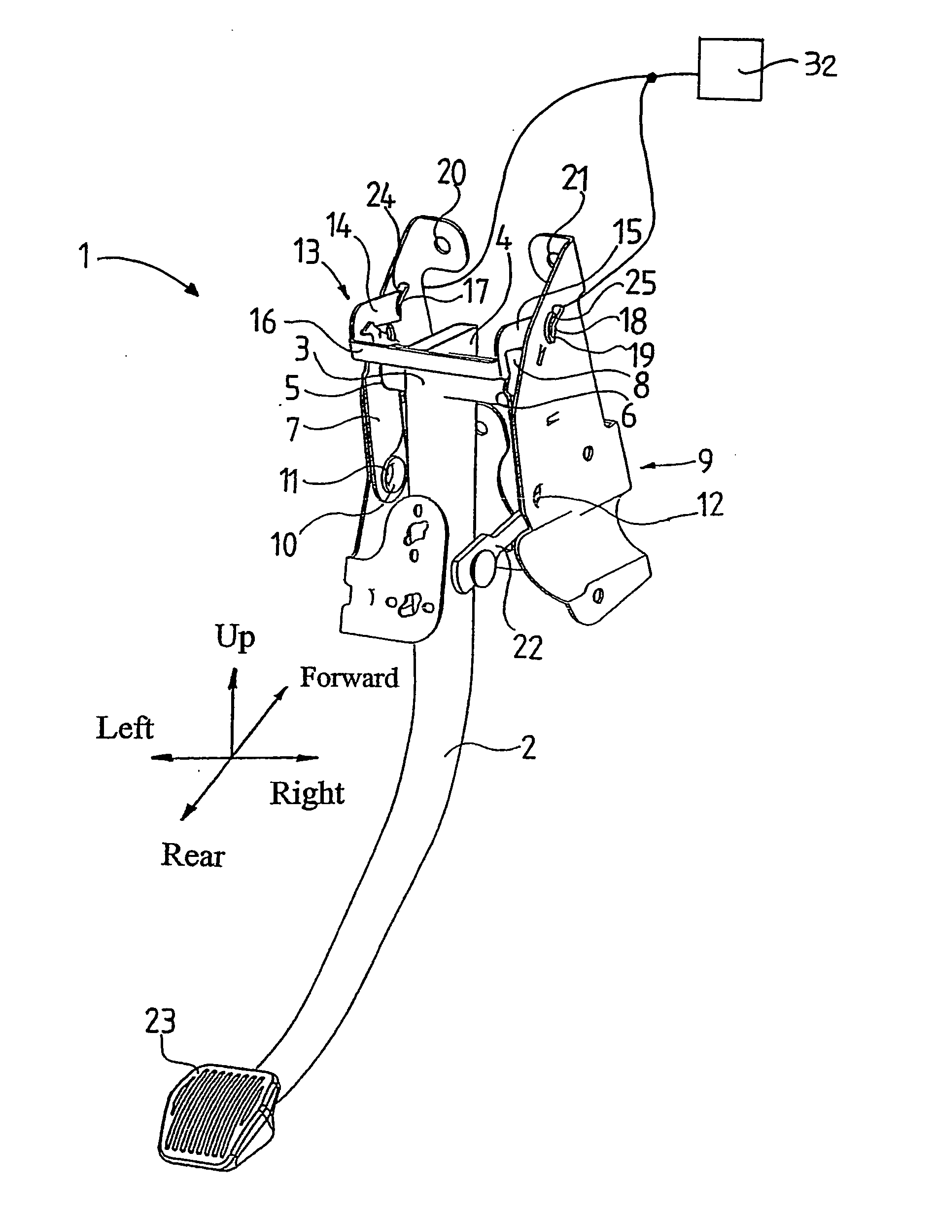
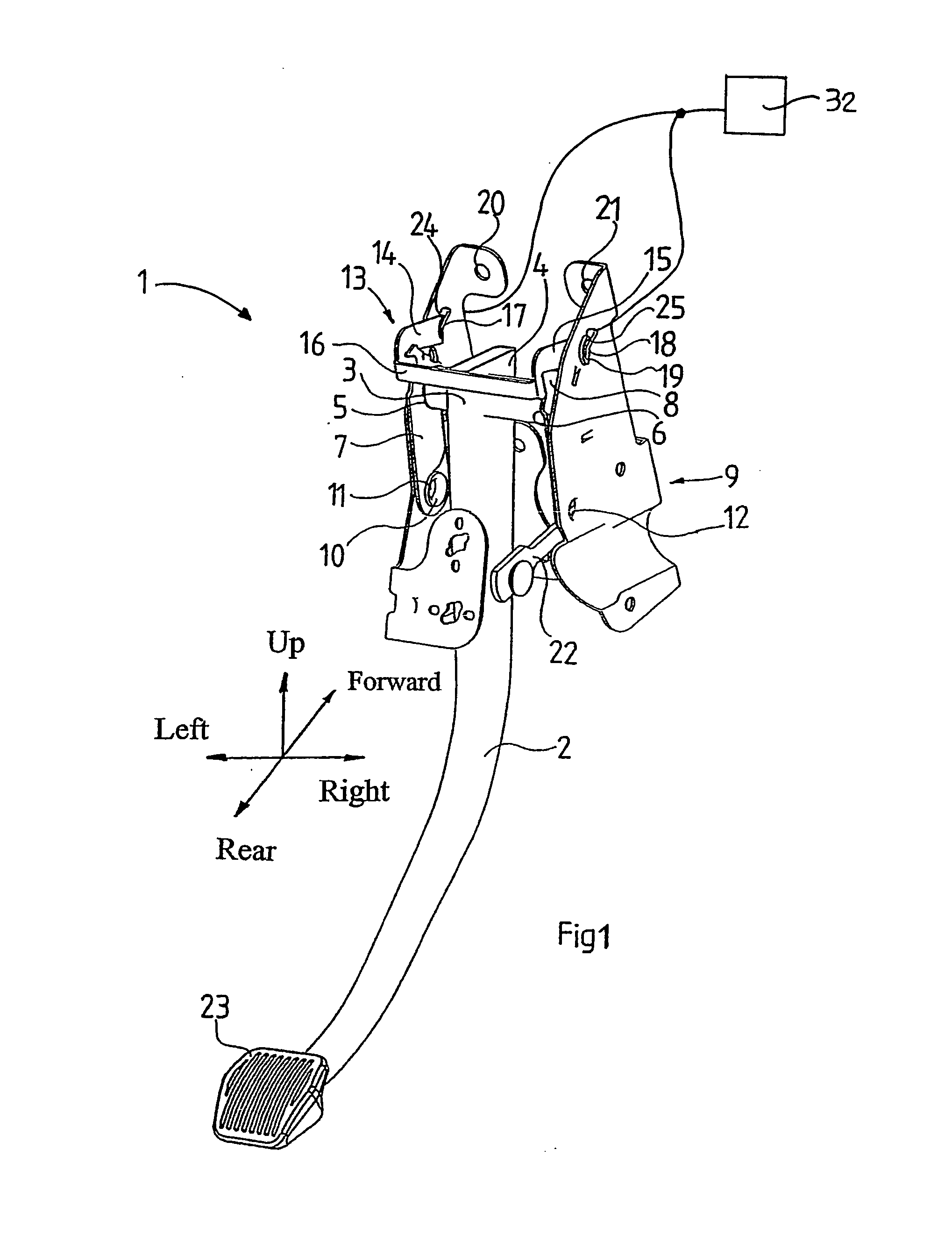
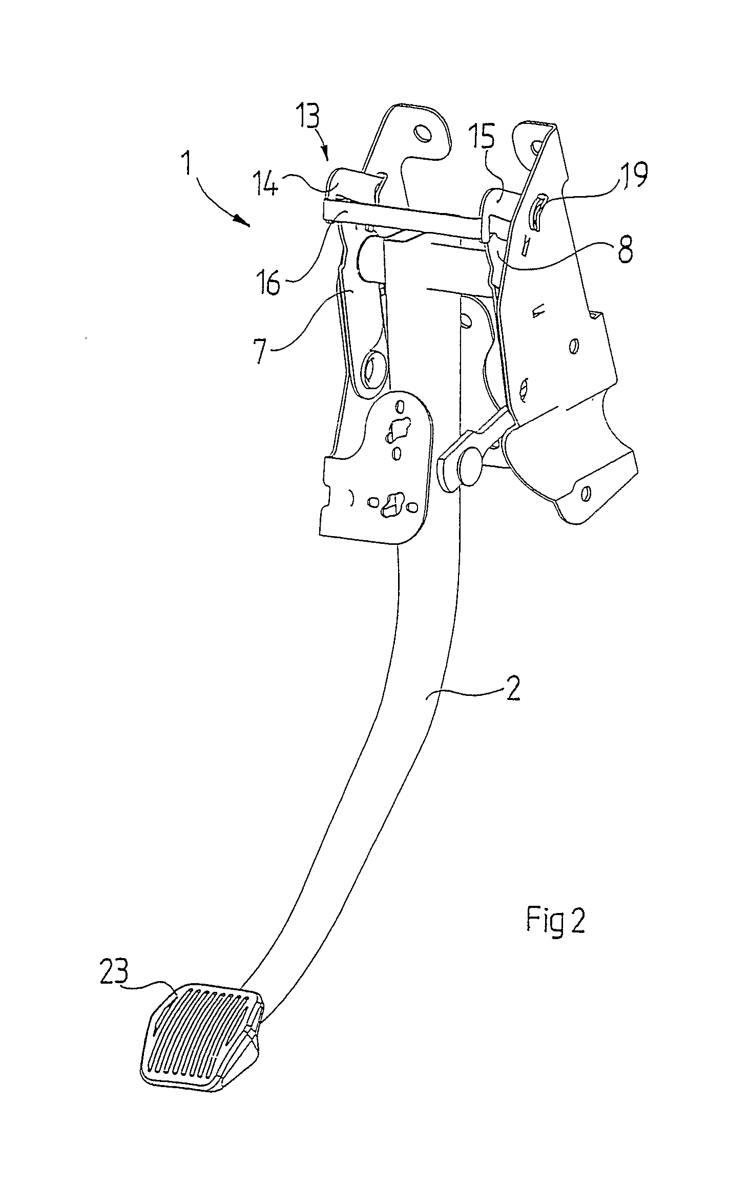
[0015] The present invention relates to a device for a pedal support in a vehicle. A pedal support is placed at the driver's position in the vehicle and may, for example, support the clutch pedal, accelerator pedal or brake pedal. In rough outline, a vehicle may be divided into a front area, passenger compartment and rear area. The front area of the vehicle includes the engine room. The passenger compartment includes the driver's seat and the passenger seats in the front and back. The rear area of the vehicle includes the luggage boot and adjacent spaces. In the front region of the passenger compartment, there is provided a substantially vertical definition which defines the passenger compartment from the front area of the vehicle. This definition is often called a bulkhead. On the bulkhead, various parts in the passenger compartment may be secured. The function of the bulkhead is to act both a securement surface and as a safety barrier for the passengers in the passenger compartmen...


PUM


Abstract

The disclosure relates to a pedal support for a vehicle, comprising a bracket (9) which is secured in a bulkhead disposed in the vehicle between the passenger compartment of the vehicle and the engine room; a first shaft (3) secured in the bracket and horizontal and transversely directed in relation to the direction of travel of the vehicle; a pedal arm (2) provided with a footplate (23) and pivotal about the first shaft; an operating device (22) which is secured in the arm (2) a distance from the first shaft and which is disposed for manoeuvring or controlling a vehicle function, for example a braking function. According to the invention, the first shaft (3) is movably disposed in the bracket (9) in the direction of travel of the vehicle, the first shaft having a normal position locked by means of a locking device (13), and the locking device being, in the event of a collision, openable for permitting displacement of the first shaft (3) to a safety position where the footplate (23) is displaced away from the legs / feet of the vehicle driver but where the function of the operating device (22) is at least partly retained.

Description

TECHNICAL FIELD [0001] The present invention relates to a pedal support for a vehicle, comprising a bracket which is secured in a bulkhead disposed in the vehicle between the passenger compartment of the vehicle and its engine room; a first shaft which is secured in the bracket and is horizontal and transversely directed in relation to the direction of travel of the vehicle, a pedal arm provided with a footplate and pivotal about the first shaft; an operating device which is secured in the pedal arm a distance from the first shaft and which is disposed for activation or control of a vehicular function, for example a braking function. BACKGROUND ART [0002] In modern motor cars, collision safety has become an increasingly important feature. Motor car safety may be improved in that an airbag catches both the driver and passengers before they hit solid parts in the passenger compartment of the motor car. The passenger compartment lies on the inside of a so-called bulkhead. The bulkhead ...

Claims


Application Information

Patent Timeline
Patent Type & Authority Applications(United States)
IPC IPC(8): G05G1/14G05G1/30G05G1/32G05G1/44
CPCG05G1/30Y10T74/20528G05G1/44G05G1/32Y10T70/5965
Inventor JOHANSSON, MATTIAS
Owner DRIVESOL WORLDWIDE
Learn More