Eureka AIR delivers breakthrough ideas for toughest innovation challenges, trusted by R&D personnel around the world.

Method and apparatus for locating gas hydrate

a gas hydrate and gas hydrate technology, applied in seismology, water-logging seismology, instruments, etc., can solve the problem of missing significant accumulations of gas hydrate, and achieve the effect of reducing permeability and high porosity

Active Publication Date: 2007-11-15
SCHLUMBERGER TECH CORP
View PDF4 Cites 67 Cited by
  • Summary
  • Abstract
  • Description
  • Claims
  • Application Information

AI Technical Summary

Benefits of technology

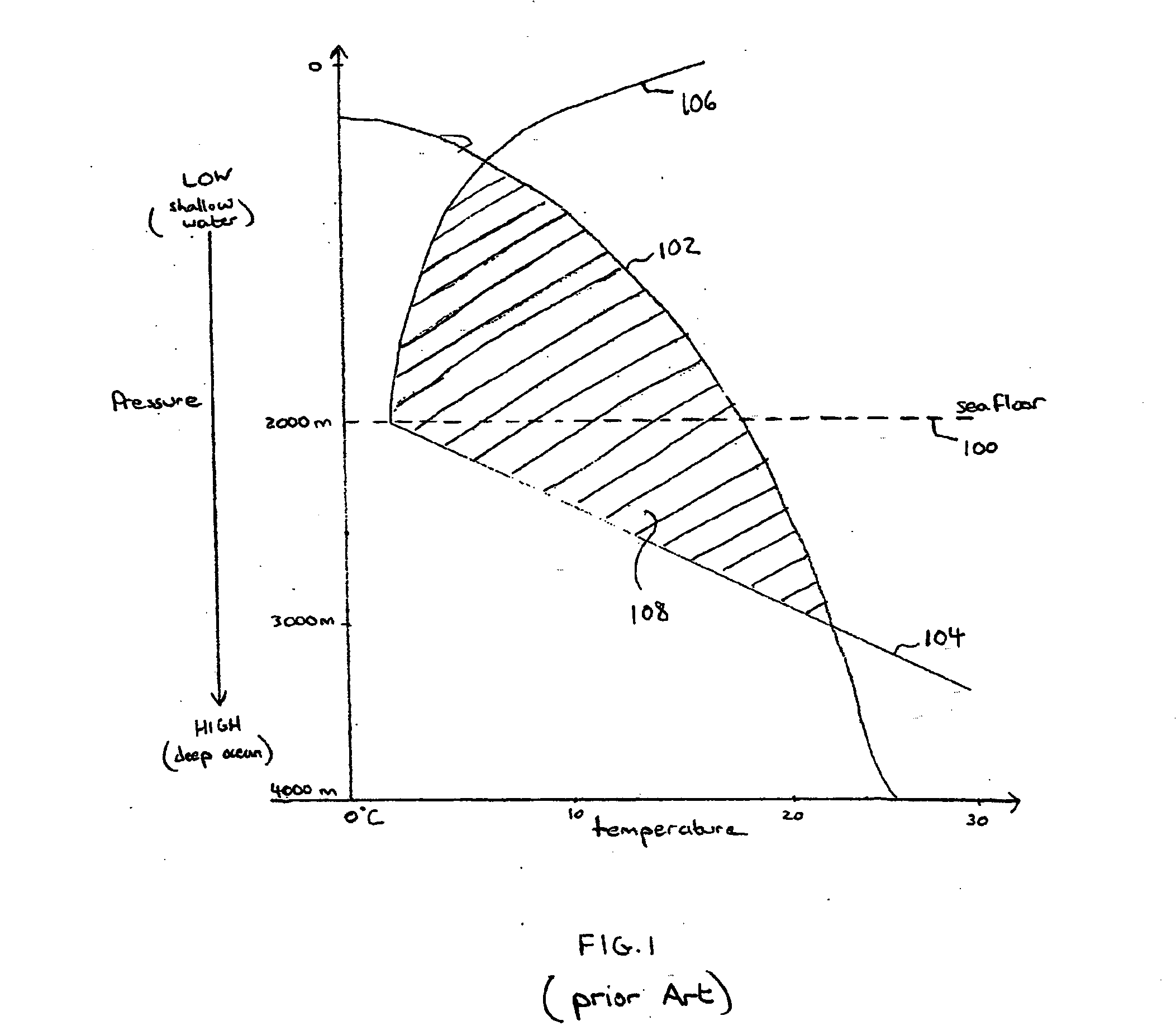
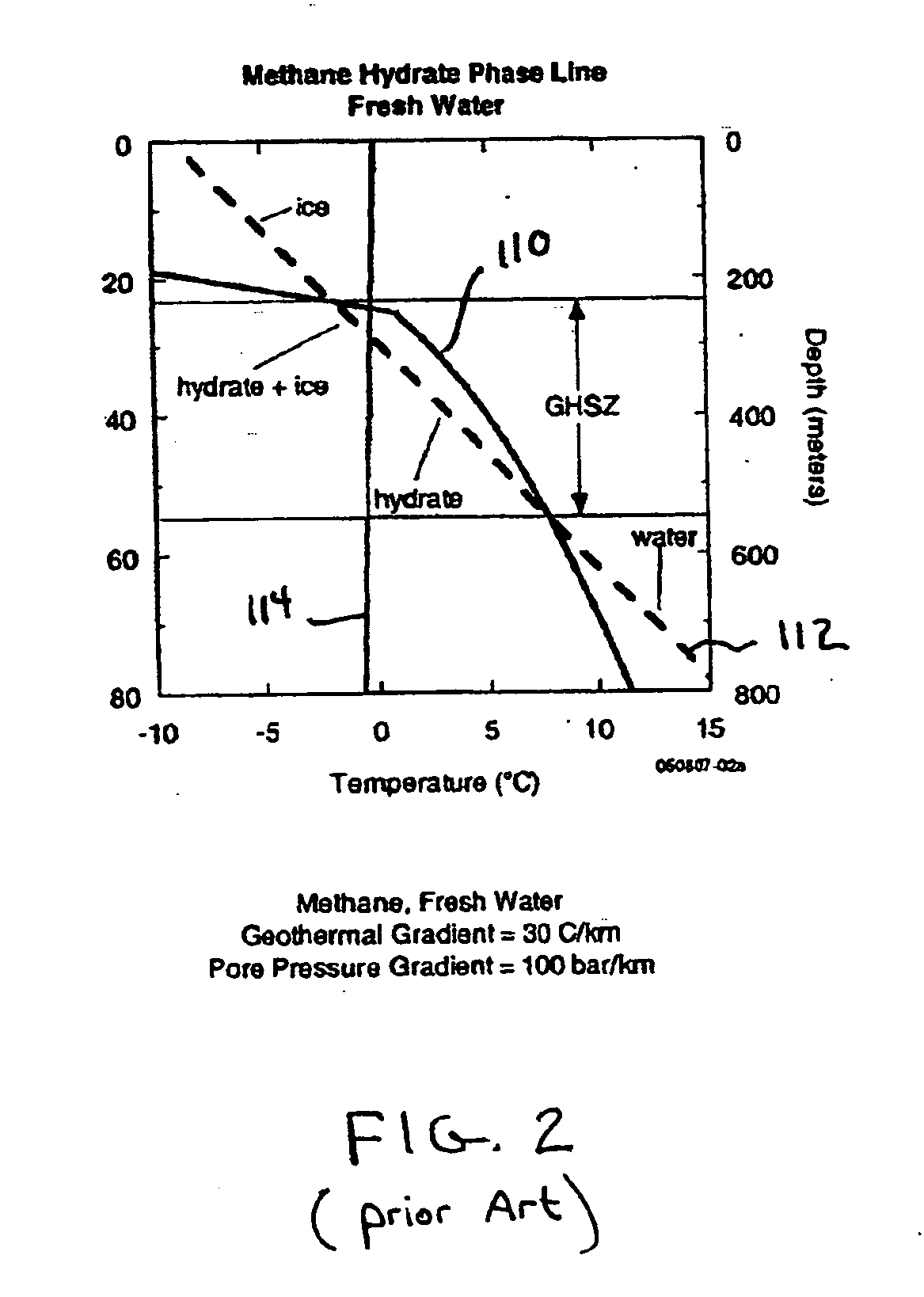
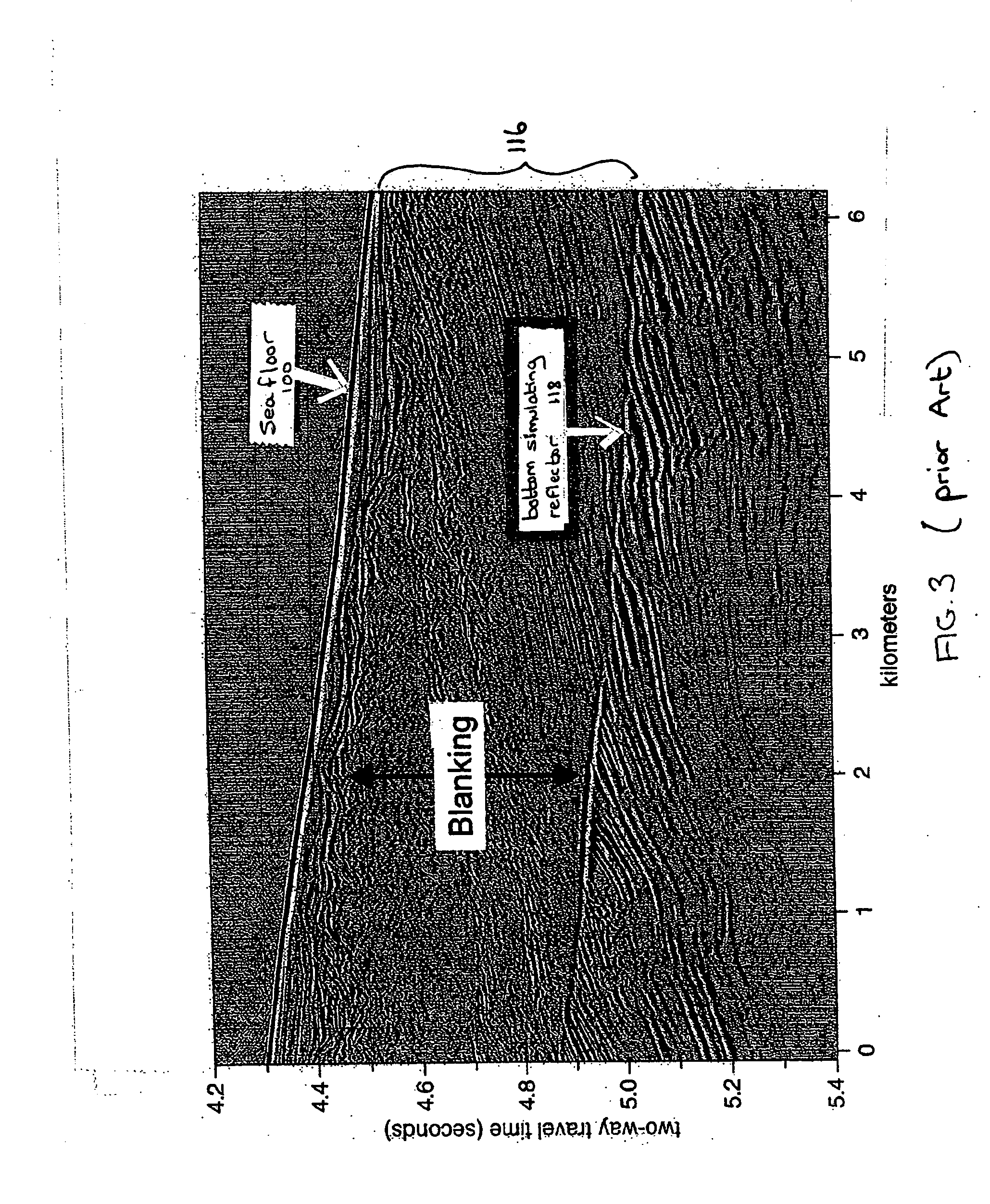
[0012] It is becoming increasingly apparent that conventional seismic and electromagnetic hydrate exploration programs, which assume the existence of horizontal, laterally extensive hydrate accumulations, may be missing significant accumulations of gas hydrate on continental slopes. According to embodiments of the invention, there are presented methods and systems that encompass an exploration paradigm that may be based, at least in part, on a particular hydrate deposit accumulation mechanism. Failure of the bottom simulating reflector to be a reliable indicator of abundant hydrate, and the seismic amplitude blanking sometimes observed coincident with the gas hydrate stability zone, are consistent with a model in which hydrate may accumulate in vertical or sub-vertical dikes. Other mechanisms may be less likely to produce abundant hydrate accumulations due to limited in situ organic carbon, reduced permeability to free or dissolved gas once hydrate forms, and the inability of hydrate to concentrate by migration to high porosity reservoir rock, as discussed below. Embodiments of this exploration paradigm may expand exploration strategy beyond exclusive reliance on traditional indicators and may incorporate geological and geomechanical reasoning.

Problems solved by technology

It is becoming increasingly apparent that conventional seismic and electromagnetic hydrate exploration programs, which assume the existence of horizontal, laterally extensive hydrate accumulations, may be missing significant accumulations of gas hydrate on continental slopes.

Method used


Image

  • Method and apparatus for locating gas hydrate
  • Method and apparatus for locating gas hydrate
  • Method and apparatus for locating gas hydrate

Examples


Embodiment Construction

[0041] Research suggests that the total amount of hydrocarbon gas trapped in gas hydrate in the near subsurface may be immense. If so, this has significant implications for the sourcing of fossil fuel and for global climate change. In addition, gas hydrates have been suggested to be one agent contributing to seafloor instability, and therefore locating and quantifying them may be important. Gas hydrate is expected to be abundant on continental slopes and there is widespread seismic evidence for very large offshore gas hydrate deposits. Therefore, it is surprising that drilling campaigns in promising regions have found very little gas hydrate. The disappointing results of marine gas hydrate exploration programs to date suggest that either gas hydrate on continental slopes is much less abundant than had been expected, or that conventional exploration paradigms are ineffective.

[0042] Conventionally, marine gas hydrate exploration prospects have been defined by seismic surveys, with th...


PUM


Abstract

An exploration paradigm for detecting and / or characterizing gas hydrate deposits using either electromagnetic or seismic surveys, that accounts for the possibility that gas hydrate may accumulate in vertical or subvertical dikes. Geologic factors, such as the presence of the gas hydrate stability zone, indications that a prolific source of gas exists (or existed) below the gas hydrate stability zone and indications that a high flux of gas could be transported into the gas hydrate stability zone, may be considered as part of an exploration strategy. Data may be collected using seismic techniques, such as a walk-away vertical seismic profile techniques, or electromagnetic surveys that are adapted to detecting the presence of vertical or subvertical dikes. In one example, data processing and acquisition techniques may be adapted to detect hydrate dikes, and do not assume a horizontally isotropic earth model.

Description

BACKGROUND [0001] 1. Field of Invention [0002] The present invention relates to systems and methods for locating gas hydrate deposits. [0003] 2. Discussion of Related Art [0004] Gas hydrates are a class of clathrate (lattice-like) compounds in which individual small molecules, commonly in the gas phase at room temperature and pressure, occupy sites within a solid crystalline matrix of water molecules. In natural gas hydrate reservoirs, the guest molecules are either pure methane or a mixture of compounds comprising natural gas. For gas hydrate deposits to form, a source of gas is required. Seeps of natural gas, generally comprising methane, are common in many parts of the world. Natural gas hydrate deposits are found in both terrestrial and marine environments. Terrestrial hydrates accumulate in and under permafrost in arctic regions. Marine gas hydrates may be found trapped in subseafloor sediments in water depths of at least about 500 meters (m). [0005] Gas hydrates form at elevat...

Claims


Application Information

Patent Timeline
IPC IPC(8): G06F19/00
CPCG01V1/288G01V3/083G01V2210/65G01V2210/647G01V3/12E21B41/0099G01N29/00G01V3/15
Inventor KLEINBERG, ROBERTHALDORSEN, JAKOB B.U.
Owner SCHLUMBERGER TECH CORP
Why Eureka
Eureka Blog
Learn More