
Precast stair tread with bolts

a precast and bolt technology, applied in the direction of treads, flooring, construction, etc., can solve the problems that the strength and integrity of the product cannot be affected by the reduction in weight, and the construction industry is particularly affected by the increase in fuel costs, so as to achieve satisfactory structural integrity and reduce weight

Inactive Publication Date: 2007-11-15
MUNSON BOARDMAN
View PDF14 Cites 4 Cited by
  • Summary
  • Abstract
  • Description
  • Claims
  • Application Information

AI Technical Summary

Benefits of technology

[0005] Accordingly, it is an object of the present invention to provide a reduced weight stair tread having satisfactory structural integrity.
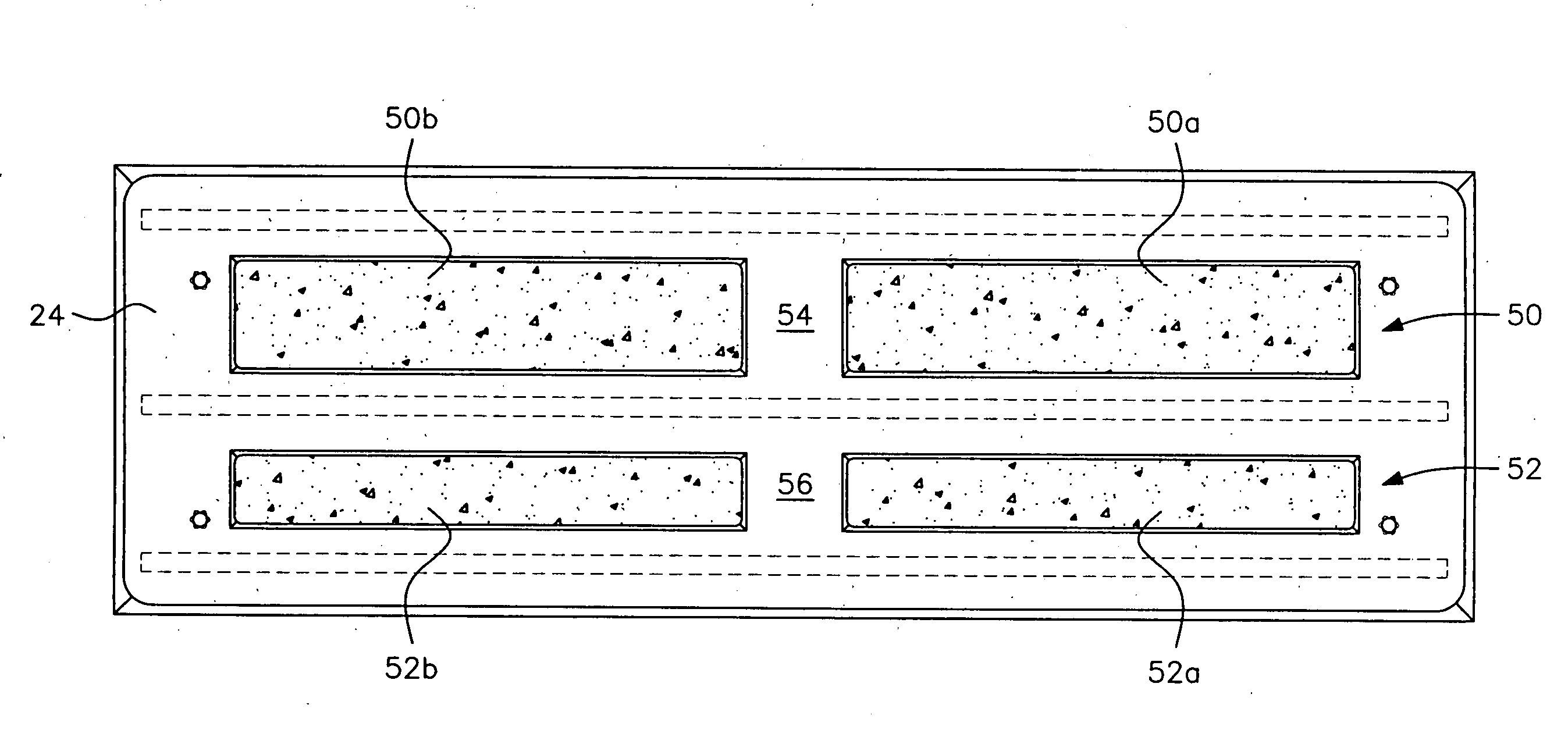
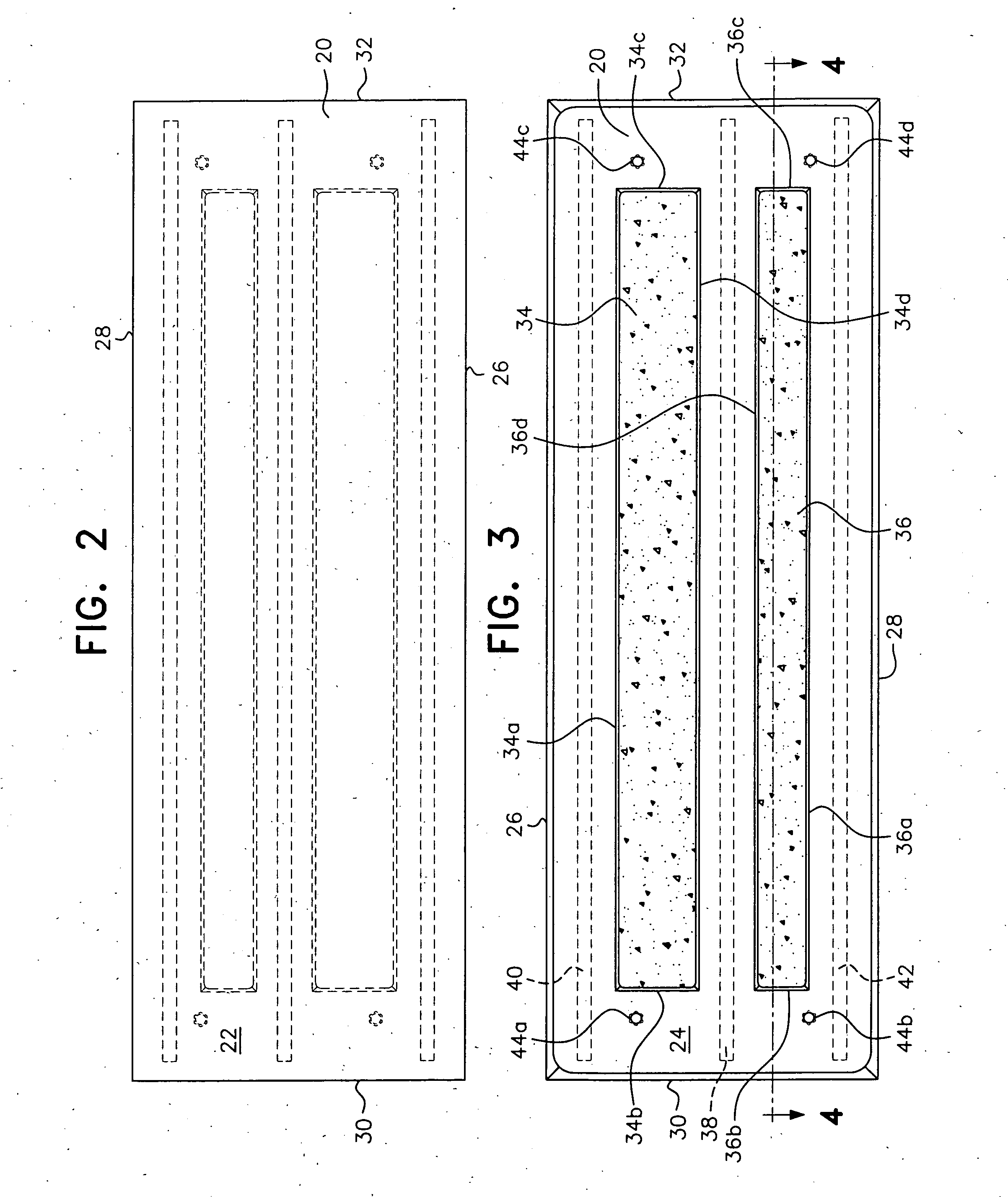
[0010] Extending lengthwise for a majority of the length of the tread are three pieces of #3 rebar. One of the pieces of rebar extends centrally through the slab. The other two pieces of rebar are located towards the front surface and rear surface of the slab, respectively. The pieces of rebar are positioned so that, in the center of the slab, the rebar lies between the two recesses. The rebars at the front surface and the rear surface lie between the external surfaces of the slab and the recesses in the slab. All surfaces of the pieces of rebar are surrounded by at least a ¾ inch radius of concrete in all directions to secure the rebar in the slab and to strengthen the stair tread.
[0014] It is therefore another object of the present invention to provide a stair tread having a reduction in weight of 30% to 40% as compared with a normal stair tread of the same dimensions.
[0015] It is another object of the present invention to provide a stair tread having a reduction in weight of 30% to 40% as compared with a normal stair tread of the same dimensions with a bottom surface of the stair tread including two recesses extending longitudinally to a depth of at least 50% of the thickness of the stair tread.

Problems solved by technology

However, the strength and integrity of the product cannot be affected by the reduction in weight.
One aspect of the construction industry particularly affected by increased fuel costs is the construction of stairways for apartment buildings, parking garages, stadiums, etc.

Method used


Image

  • Precast stair tread with bolts
  • Precast stair tread with bolts
  • Precast stair tread with bolts

Examples


Embodiment Construction

[0026] In describing a preferred embodiment of the invention illustrated in the drawings, specific terminology will be resorted to for the sake of clarity. However, the invention is not intended to be limited to the specific terms so selected, and it is to be understood that each specific term includes all technical equivalents which operate in a similar manner to accomplish a similar purpose.

[0027] With reference to the drawings, in general, and to FIGS. 2 through 5, in particular, a precast stair tread embodying the teachings of the subject invention is generally designated as 10.

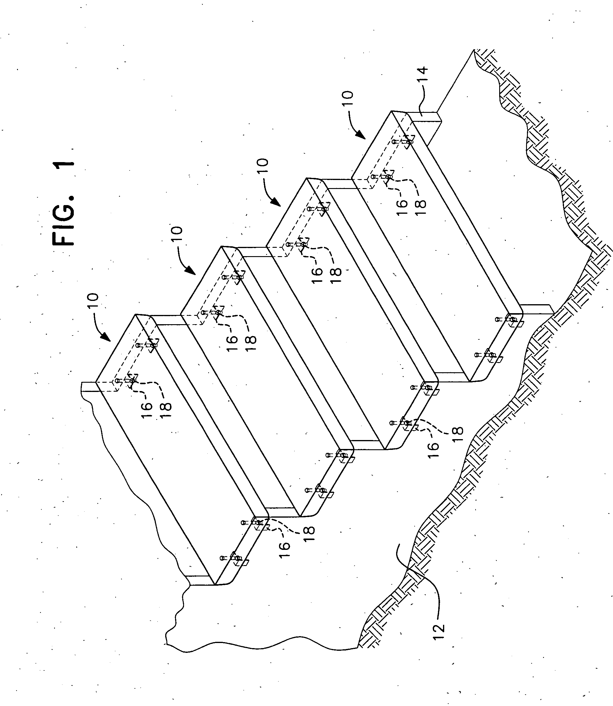
[0028] With reference to its orientation in FIG. 1, the stair tread is shown in its position of use supported by two spaced apart stair frames 12, 14. The stair frames have been assembled at a construction site for enabling transit between two floors by an in situ formed staircase.

[0029] A plurality of precast stair treads 10 of the present invention are transported to the construction site for assembl...


PUM


Abstract

A stair tread having a width of 10, 11 or 12 inches. The tread length varies from 32 inches up to 60 inches in length. The thickness of the tread will usually be 2¼ or 3 inches thick, with a draft of ¼ inch and exposed edges having a ⅜ inch radius. A significant reduction in weight is obtained by forming two rows of recesses in a bottom surface of the stair tread. On a tread having a thickness of 2¼ inches, the depth of the recesses is 1¼ inches deep. On a tread having a thickness of 3 inches, the recesses have a depth of 2 inches. Therefore, the depth of the recesses will be at least 50% of the thickness of the tread.

Description

FIELD OF THE INVENTION [0001] The present invention relates to manufactured stair treads which are precast and then transported to a remote construction site and secured in place to two spaced stair frames. The stair tread is formed of a self-supporting slab of concrete having weight reducing recesses. BACKGROUND OF THE INVENTION [0002] With the increasing cost of fuel, it is a primary objective of the construction industry to reduce fuel expenditures by reducing the weight of transported products. However, the strength and integrity of the product cannot be affected by the reduction in weight. [0003] One aspect of the construction industry particularly affected by increased fuel costs is the construction of stairways for apartment buildings, parking garages, stadiums, etc. Typically, component parts of the stairway are manufactured close to a source of concrete materials. Individual component parts are then transported to the remote construction site for installation. Due to the in...

Claims


Application Information

Patent Timeline
IPC IPC(8): E04F15/00
CPCE04F11/116
Inventor MUNSON, BOARDMAN
Owner MUNSON BOARDMAN
Learn More