
Loosely coupled lancet

Inactive Publication Date: 2007-11-01
FACET TECH LLC
View PDF29 Cites 104 Cited by
  • Summary
  • Abstract
  • Description
  • Claims
  • Application Information

AI Technical Summary

Benefits of technology

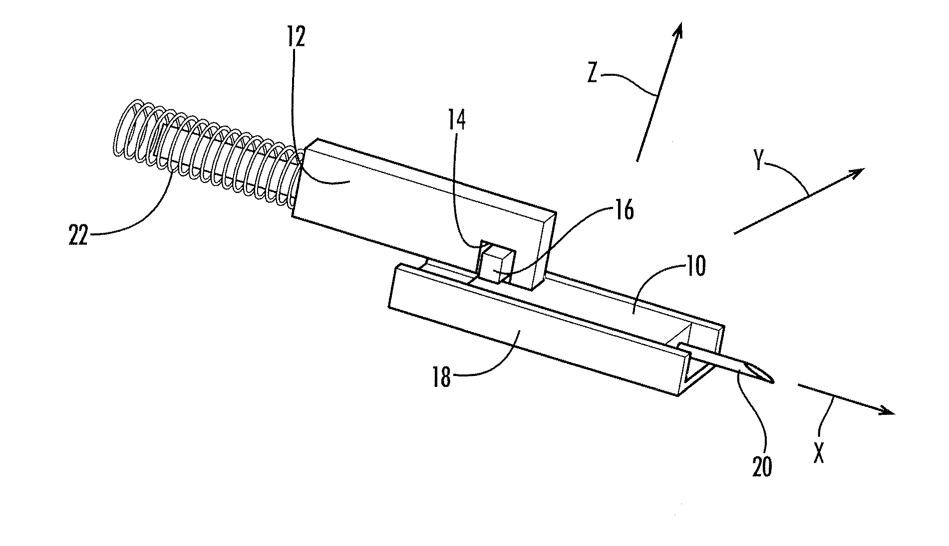
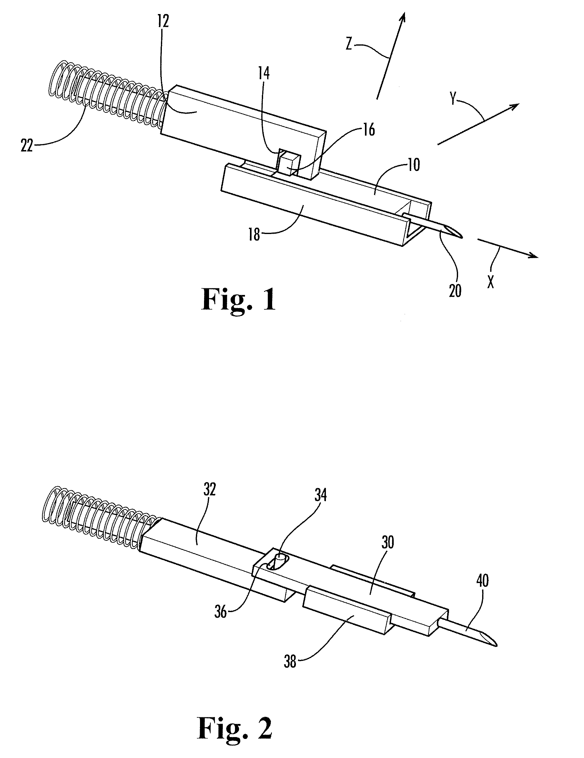
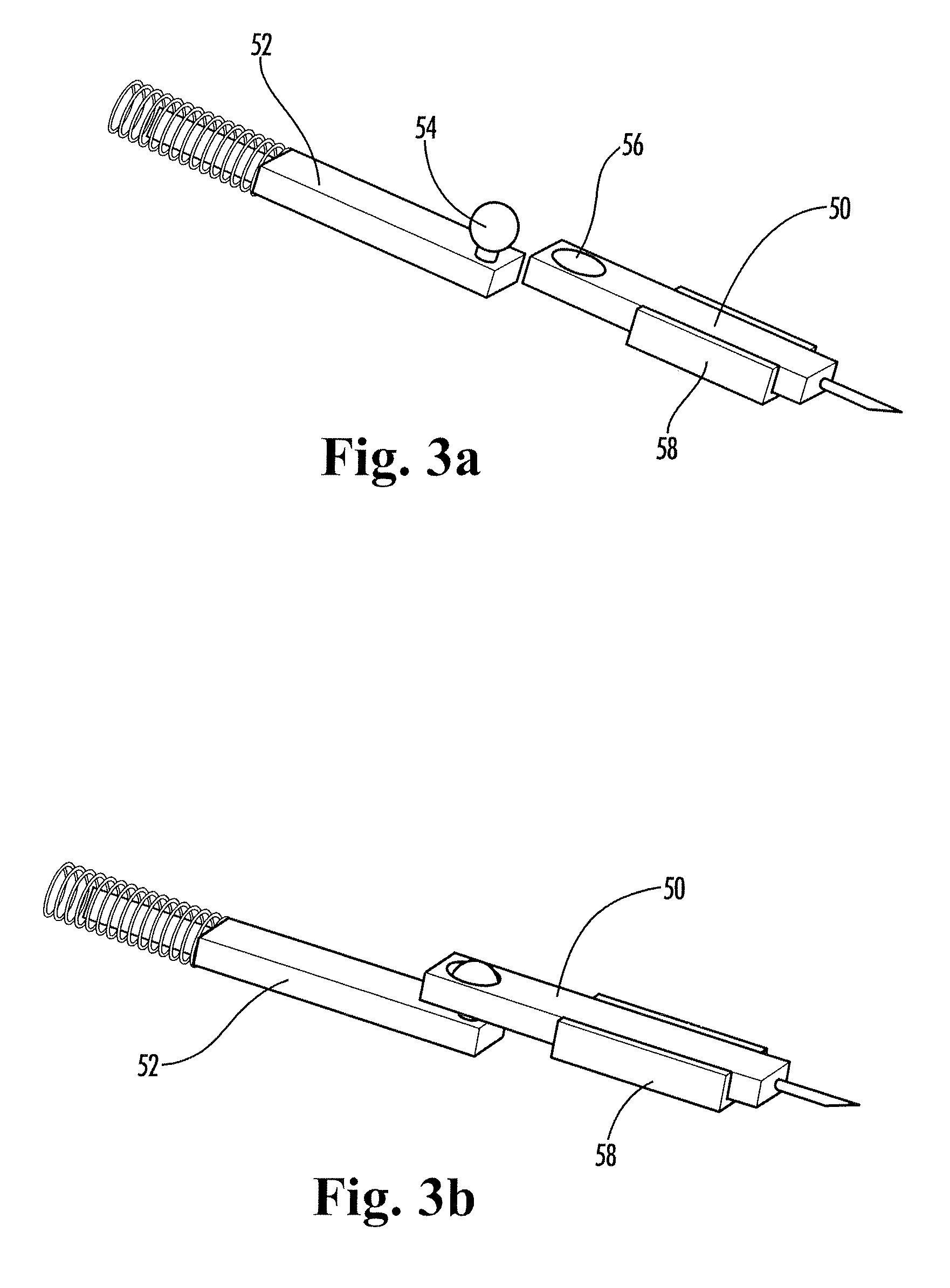
[0007] In example forms, the lancing device and lancet of the present invention reduce pain by eliminating or minimizing non-axial movement and misalignment of the lancet during a lancing procedure. The lancet is not tightly coupled to the moving parts of the driving mechanism, but rather is loosely coupled thereto. In this manner, the lancet coupling of the present invention provides one or more degrees of freedom of motion between the lancet and the drive mechanism of the lancing device. This coupling mechanism and method preferably pulls and pushes the lancet along a linear path coincident with the longitudinal axis of the lancet needle, preferably using a single point of contact in either direction. The lancet is preferably further guided by a smooth non-moving track or other guidance feature, to produce a straighter and smoother lancet travel throughout the lancet stroke. This allows the lancet to stay on axis and not be affected by vibrations and off-axis travel of the drive mechanism. The lancet of the present invention therefore projects into and out of the skin along a straight linear path, without significant lateral movement. Vibrations and misalignment from the driver, piston, or springs of the lancing device are not directly transferred to the lancet. As a result, a much smoother and straighter lancet travel into and out of the skin is achieved, leading to reduction in pain experienced by the subject.

Problems solved by technology

Even small amounts of off-axis vibration or misalignment can cause tearing or pulling of the skin during the lancing sequence, increasing pain to the subject.
A significant disadvantage of this approach is that any off-center movement or angulation of the drive mechanism translates directly into the lancet.
Another disadvantage is that any vibrations introduced by the drive springs and return springs of the lancing device tend to be communicated to the lancet, potentially leading to increased pain to the subject.

Method used


Image

  • Loosely coupled lancet
  • Loosely coupled lancet
  • Loosely coupled lancet

Examples


Embodiment Construction

[0019] The present invention may be understood more readily by reference to the following detailed description of the invention taken in connection with the accompanying drawing figures, which form a part of this disclosure. It is to be understood that this invention is not limited to the specific devices, methods, conditions or parameters described and / or shown herein, and that the terminology used herein is for the purpose of describing particular embodiments by way of example only and is not intended to be limiting of the claimed invention. Also, as used in the specification including the appended claims, the singular forms “a,”“an,” and “the” include the plural, and reference to a particular numerical value includes at least that particular value, unless the context clearly dictates otherwise. Ranges may be expressed herein as from “about” or “approximately” one particular value and / or to “about” or “approximately” another particular value. When such a range is expressed, anothe...


PUM


Abstract

A low-pain lancing device includes a drive mechanism for loosely engaging a lancet and driving the lancet along an axial path. The drive mechanism has a first coupling element and the lancet has a second coupling element, which together form a loose coupling therebetween, wherein interaction between the first and second coupling elements permits a degree of freedom of movement between the lancet and the drive mechanism in a lateral direction, perpendicular to the axial path of travel of the lancet, to prevent non-axial movement of the lancet tip during lancing and thereby reduce pain experienced by the subject.

Description

CROSS-REFERENCE TO RELATED APPLICATIONS [0001] This application is a continuation-in-part of and claims priority benefit to U.S. patent application Ser. No. 10 / 505,352 filed Aug. 19, 2004, and is a continuation-in-part of and claims priority benefit to U.S. patent application Ser. No. 10 / 987,591 filed Nov. 12, 2004; both of which are incorporated herein by reference in their entireties.TECHNICAL FIELD [0002] The present invention relates generally to medical devices, and more particularly to low-pain lancing devices for medical diagnostic sampling. BACKGROUND OF THE INVENTION [0003] Lancing devices are commonly used to penetrate the skin of a subject and obtain a sample of blood or other body fluid, as in the testing of blood sugar levels by diabetics. Typically, a lancet having a sharp point is translationally mounted within a lancing device. The lancet is driven by a spring or other biasing means to cause the sharp point to extend a small distance through an opening in the housing...

Claims


Application Information

Patent Timeline
IPC IPC(8): A61B5/151
CPCA61B5/1411A61B5/150022A61B5/150152A61B5/150412A61B5/150519A61B5/150541A61B5/150618A61B5/15107A61B5/15117A61B5/1513A61B5/15186
Inventor VANHIEL, BRIAN D.KOEPPEL, BRADLEY S.CONWAY, WILLIAM E.RUF, CHRISTOPHER J.IRWIN, JOHN C.ROBBINS, AVI M.LATHROP, RAY
Owner FACET TECH LLC
Learn More