
Treatment of spent caustic refinery effluents

a technology for caustic effluent and refinery effluent, which is applied in the direction of liquid degasification, combustion types, separation processes, etc., can solve the problems of insufficient concentration and combustion of submerged combustion methods, and the effluent has been considered essentially useless, so as to prevent the dissipation of carbon dioxide into the atmosphere

Inactive Publication Date: 2007-11-01
DUESEL BERNARD F JR +2
View PDF99 Cites 34 Cited by
  • Summary
  • Abstract
  • Description
  • Claims
  • Application Information

AI Technical Summary

Benefits of technology

[0016] According to another aspect of the invention, at least some of the fuel used to supply combustion gas to the submerged combustion gas evaporator is landfill gas and the carbon dioxide content of the combustion gas is used to convert the caustic constituent of the effluent to a carbonate, thereby preventing dissemination of the carbon dioxide into the atmosphere.

Problems solved by technology

Traditionally such effluents have been considered essentially useless waste streams but have required significant processing before disposal to avoid contamination of the environment.
Pat. No. 3,966,594, treatment of waste water containing water-soluble organic substances in various ways is described and the submerged combustion method is stated to be industrially insufficient in terms of concentration and combustion.

Method used


Image

  • Treatment of spent caustic refinery effluents
  • Treatment of spent caustic refinery effluents
  • Treatment of spent caustic refinery effluents

Examples


Embodiment Construction

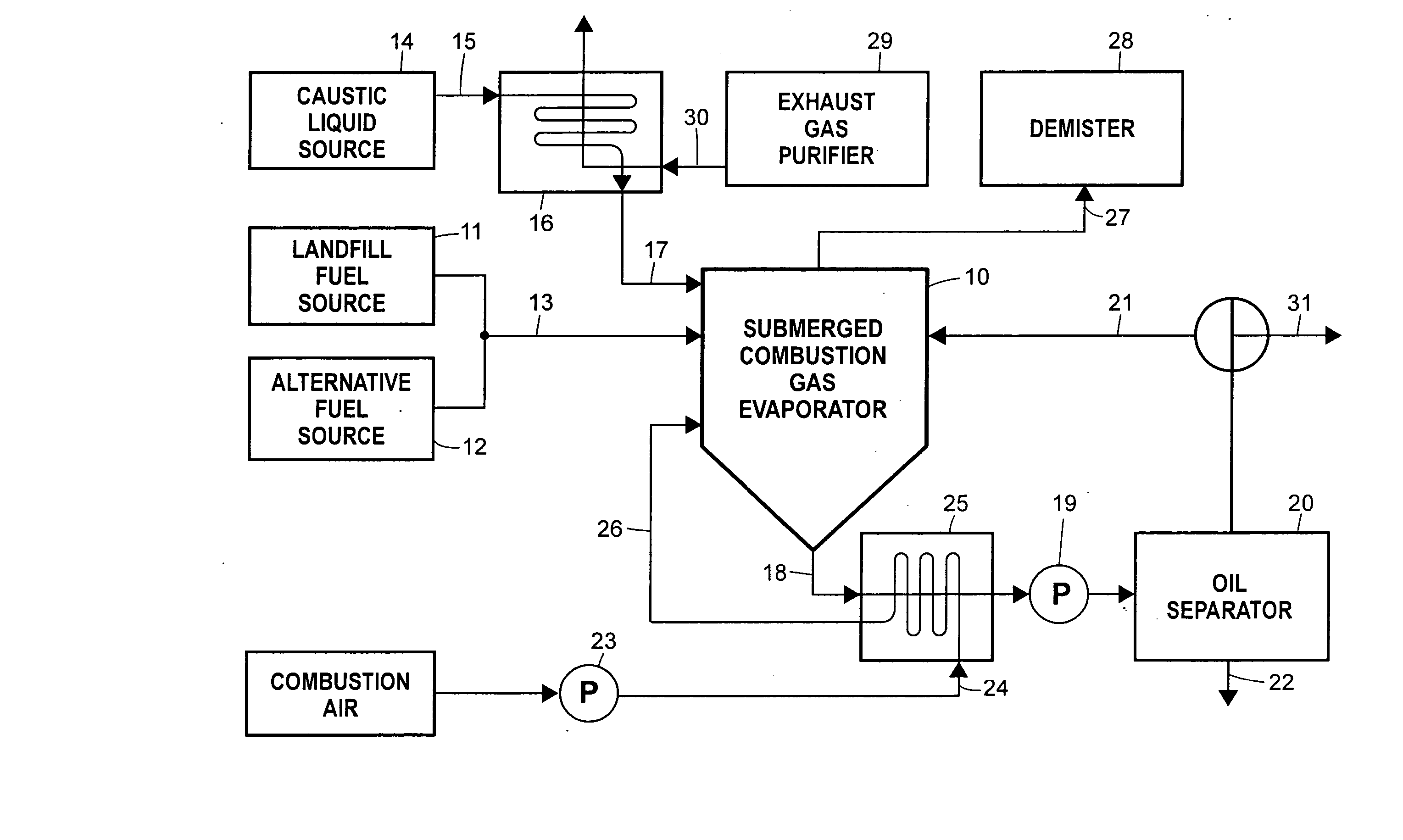
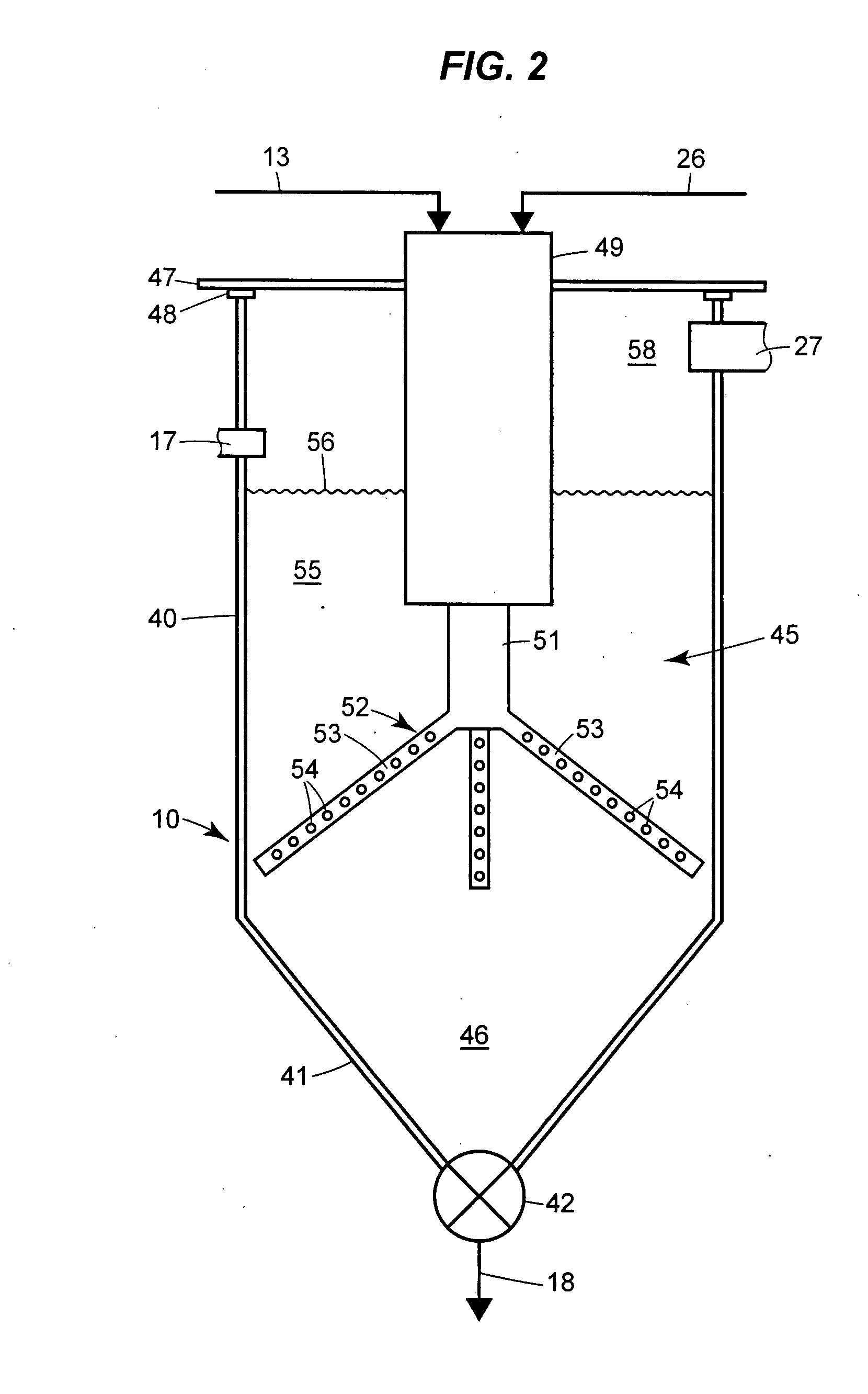
[0022] In the representative arrangement for carrying out the process of the invention schematically illustrated in FIG. 1, a submerged combustion gas evaporator 10, which is described in more detail in connection with FIG. 2, receives combustible gas from a landfill or other biogas source 11 or from an alternative fuel source 12 providing natural gas, propane, butane or the like or providing a liquid fuel such as waste petroleum oils or the like or from both. The evaporator 10 may be operated on a batch, batch-continuous, or continuous basis and the fuel gas from the sources 11 and 12 may be collected and stored for use or be supplied continuously in accordance with the needs of the evaporator. In one embodiment the system is located closely adjacent to a landfill from which landfill gases are conveniently available, but, if desired, landfill gases may be piped or transported from one or more landfills at remote locations to processing stations adjacent to a source of caustic efflu...


PUM

PropertyMeasurementUnit
temperatureaaaaaaaaaa
pressureaaaaaaaaaa

Abstract

In the methods for treatment of caustic effluents described in the specification, a spent caustic refinery effluent is supplied to a submerged combustion gas evaporator in which hot combustion gas containing carbon dioxide is injected into the caustic liquid to concentrate the liquid and convert a hydroxide constituent to a carbonate. Where the caustic effluent is from a petroleum refinery, oil in the waste liquid is separated from the aqueous constituent before, during or after concentration.

Description

BACKGROUND OF THE INVENTION [0001] This invention relates to processes for treating spent caustic effluents, for example, effluents from petroleum refineries, aluminum manufacturing, food processing or the like. [0002] Many industrial operations generate dilute spent caustic effluents such as petroleum refining processes. A typical dilute spent caustic effluent from such refineries may contain about 5% to 12% sodium hydroxide (w / w) with varying but significant quantities of organic compounds that include a range of mercaptans, sulfidic oils, naphthenic acids, cresylic acids and derivatives. Included in the mixture are lesser quantities of other inorganic and organic compounds. In addition, a petroleum refinery effluent may contain approximately 5% to 20% by volume of oil along with the aqueous caustic solution. Traditionally such effluents have been considered essentially useless waste streams but have required significant processing before disposal to avoid contamination of the env...

Claims


Application Information

Patent Timeline
Patent Type & Authority Applications(United States)
IPC IPC(8): B01D1/00F23G7/04B01D1/14B01D17/025B01D17/028B01D17/038B01D19/00B01D21/00B01D53/38B01D53/62B01D53/74C02F1/02C02F1/04C02F1/20
CPCB01D1/0058C10G19/08B01D21/0024B01D1/14B01D21/302B01D21/34
Inventor DUESEL, BERNARD F. JR.GIBBONS, JOHN P.RUTSCH, MICHAEL J.
Owner DUESEL BERNARD F JR
Learn More