
Deflectable tip videoarthroscope

Active Publication Date: 2007-10-25
ARTHREX
View PDF27 Cites 100 Cited by
  • Summary
  • Abstract
  • Description
  • Claims
  • Application Information

AI Technical Summary

Benefits of technology

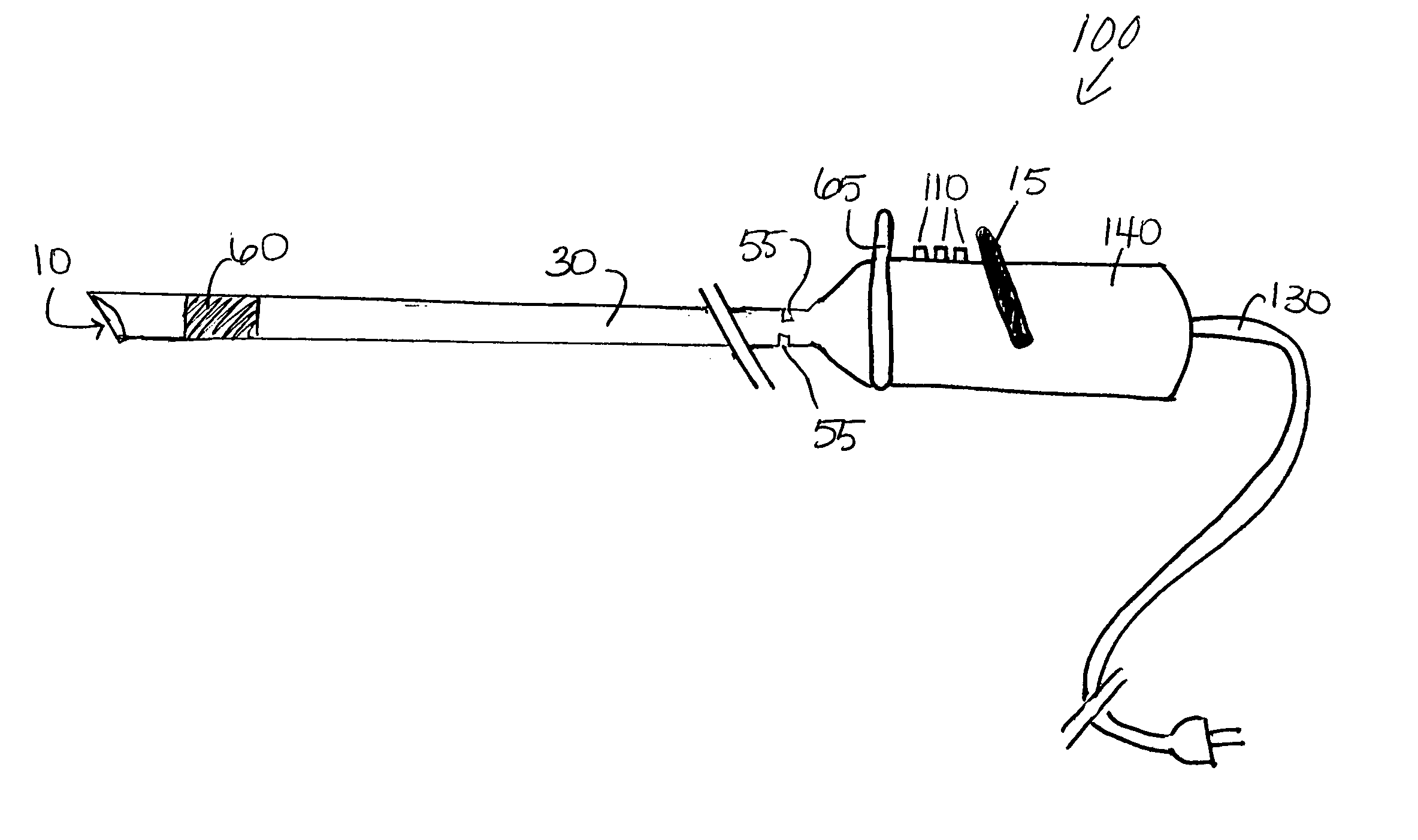
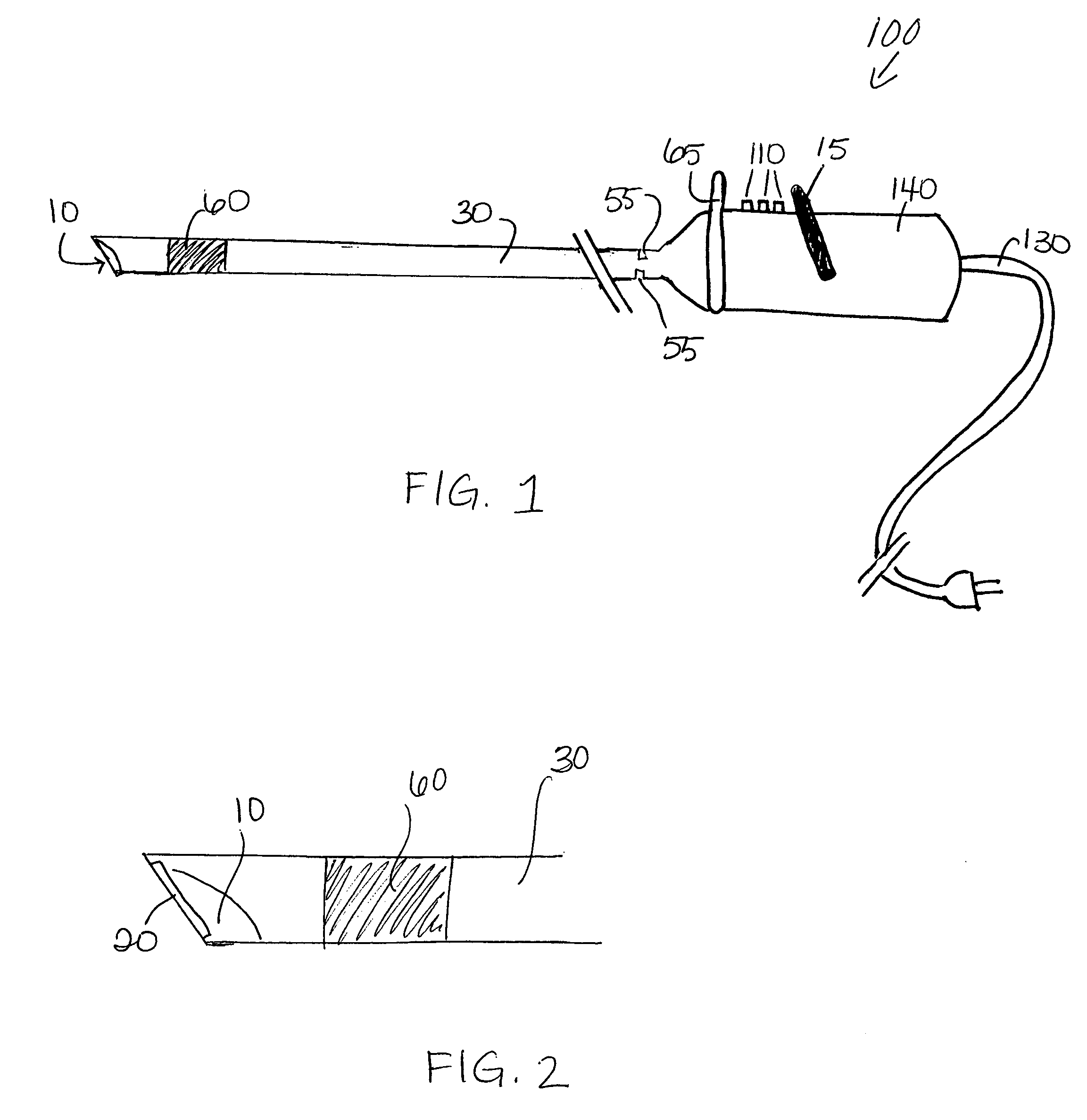
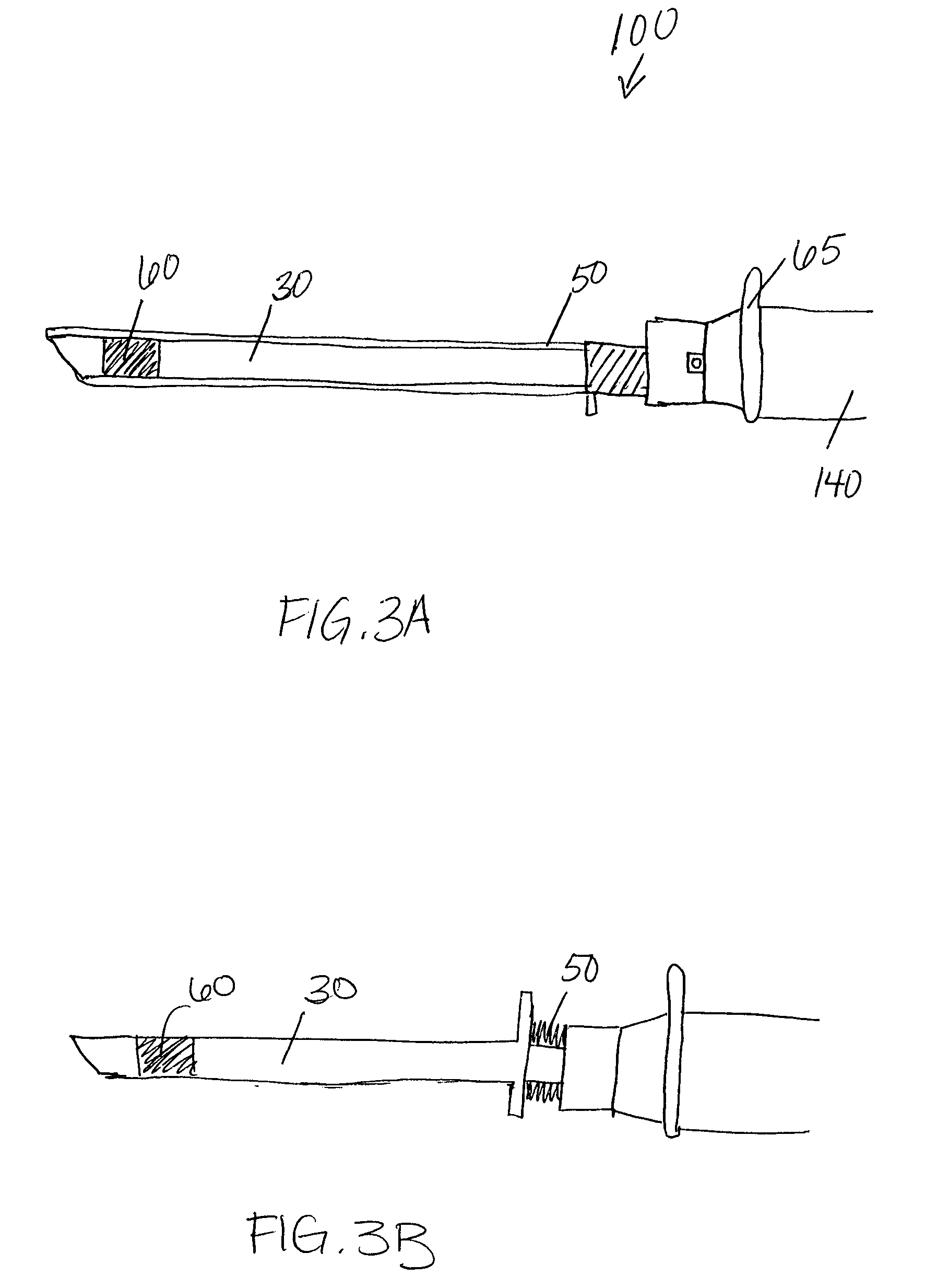
[0012] The present invention provides a 30 degree angled deflectable tip videoarthroscope of 5.4 mm diameter or smaller comprising a miniaturized chip-in-tip CCD with four-way angulations mounted on the distal end of the arthroscope. The deflectable tip videoarthroscope of the present invention may be provided with a replaceable distal window made of a thin material (such as polycarbonate or acrylic) or a glass (sapphire or other) with very high light transmission properties, connected to a sheathing system that is disposable or limited-reusable. This replaceable window / sheath could be discarded if a shaver burr or ablation probe contacts the lens. This design would protect the distal window of the videoarthroscope during use and would reduce scope repair costs and system down-time. Optionally, the deflectable tip videoarthroscope of the present invention additionally comprises a steering wheel, which allows 360 degree rotation of the instrument during arthroscopic procedures.

Problems solved by technology

Orthopedic physicians are frequently challenged when performing arthroscopic surgery because of the limitations of the design and technology of the optical / video systems and instruments.
However, to duplicate the effectiveness of open surgery, which offers a three-dimensional perspective of the joint, a physician must adapt to a more challenging technique, using rigid scopes and a camera that transmits a video image onto a two-dimensional television or LCD monitor.
Thus, the currently available conventional arthroscopic equipment poses some major challenges for physicians.
Considering the space constraints, the patient's anatomy, and the complexity of repair that may need to be performed, rigid arthroscopes do not easily allow 360 degrees of visualization inside the joint without switching to different portals or scope angles.
This often makes it difficult for a physician to orient himself correctly, perform a proper diagnosis of anatomy and pathology, or visualize his instruments as they are being introduced into or used within the joint.
In addition, since conventional arthroscopes are linear in design, they are typically rigid and do not allow for any flexibility of movement around anatomical structures.
However, human joint cavities are not composed of straight vectors and right-angled corners.
Hence, rigid scopes and instruments limit the mobility and access of physicians into all areas of the joint, which affects a physician's ability to perform the best, or at least the most efficient, repair possible.
Other limitations of current optics / scopes and instruments include the fact that linear / direct-vector scopes and instruments are not able to reach all areas of the joint, especially when steering over or around anatomic structures.
Rod-lens arthroscopes are also fragile and are easily damaged by reprocessing, handling and intra-operative use.
They are also prone to fogging, scratched lenses and material build-up on the windows, all of which reduce image quality.
Another limitation of conventional scopes relates to the optical chain, which is composed of three separate components: the scope, the light cable, and the camera head.
This design is cumbersome and inefficient for today's standards because all three components must be purchased separately, sterilized, and then assembled for surgery.
Excessive cables in the sterile field clutter workflow and operating room efficiency, as well as increase the risk of cable damage during daily use, cleaning / handling and sterilization.
Video resolution may be lost using a conventional rod-lens scope and camera head because the joint cavity must first be illuminated through a series of fiber optic bundles (light cable and the scope).
If any one of the components in this optical chain is dirty, not working correctly, or slightly damaged, the resolution and image quality sent to the monitor or peripheral devices is compromised.
The scopes, light cables, and camera heads offered by most surgical companies are not durable enough for autoclave sterilization.
Companies that do not offer an autoclave compatible video / optical chain are not meeting the needs of the global orthopedic customer market.

Method used


Image

  • Deflectable tip videoarthroscope
  • Deflectable tip videoarthroscope
  • Deflectable tip videoarthroscope

Examples


Embodiment Construction

[0025] The present invention provides a 30 degree angled deflectable tip videoarthroscope using a miniaturized CCD with four-way angulations mounted on the tip of the instrument. Preferably, the deflectable tip videoarthroscope of the present invention may be provided with a distal window made of a thin material (such as polycarbonate or acrylic) or a glass (sapphire or other) with very high light transmission properties, connected to a sheathing system that is disposable or limited-reusable. This replaceable window / sheath could be discarded if a shaver burr or ablation probe contacts the lens. This design would protect the distal window of the videoarthroscope during use and would reduce scope repair costs and system down-time. Preferably, the deflectable tip videoarthroscope may further comprise a steering wheel, which allows 360 degree rotation of the instrument during arthroscopic procedures with an integrated electronic of manual CCD horizontal image stabilization system.

[0026...


PUM


Abstract

A deflectable tip videoarthroscope of 5.4 mm diameter or smaller, comprising a miniaturized chip-in-tip CCD with four-way angulations mounted on the distal end of the arthroscope. The deflectable tip videoarthroscope may be provided with a replaceable distal window made of a thin material (such as polycarbonate or acrylic) or a glass (sapphire or other) with very high light transmission properties, connected to a sheathing system that is disposable or limited-reusable, which could be discarded if a shaver burr or ablation probe contacts the lens. This design protects the distal window of the videoarthroscope during use and reduces scope repair costs and system down-time. The deflectable tip videoarthroscope may additionally include a steering wheel, which allows 360 degree rotation of the instrument during arthroscopic procedures. The videoarthroscope may further include an irrigation channel or a wireless imager control system.

Description

CROSS REFERENCE TO RELATED APPLICATIONS [0001] This application claims the benefit of U.S. Provisional Application No. 60 / 789,167, filed Apr. 5, 2006.FIELD OF THE INVENTION [0002] The present invention relates to instruments for arthroscopic surgery and, more particularly, to videoarthroscopes. BACKGROUND OF THE INVENTION [0003] Orthopedic physicians are frequently challenged when performing arthroscopic surgery because of the limitations of the design and technology of the optical / video systems and instruments. The goal of arthroscopy is to perform minimally invasive surgery as an alternative to open surgery. Arthroscopy has proven to be safer, less painful and have a faster recovery time for patients when compared to open surgery. However, to duplicate the effectiveness of open surgery, which offers a three-dimensional perspective of the joint, a physician must adapt to a more challenging technique, using rigid scopes and a camera that transmits a video image onto a two-dimensiona...

Claims


Application Information

Patent Timeline
IPC IPC(8): A61B1/04
CPCA61B1/00016A61B1/0051A61B1/042A61B1/00096A61B1/00041A61B1/00078A61B1/317A61B1/0004
Inventor SEIFERT, ALEXANDER
Owner ARTHREX
Learn More