
Barrel plating device

Inactive Publication Date: 2007-10-25
YAMAMOTO MS
View PDF5 Cites 10 Cited by
  • Summary
  • Abstract
  • Description
  • Claims
  • Application Information

AI Technical Summary

Benefits of technology

[0013]With this configuration, the drum and the bar-shaped conductive member integrally rotate. Therefore, a gap is not formed between the bar-shaped conductive member and the objects to be plated in the drum, which prevents a generation of a high-current-density part. As a result, there is prevented an occurrence of burnt deposit in a plating film formed on a surface of the plated object.
[0030]In addition, according to the present invention, there is provided a barrel plating device in which a replacement of the drum and introduction and removal of the objects are facilitated to thereby workability, and at the same time, the drum is stably rotated without coming off of a use position during the operation of the plating device.

Problems solved by technology

As a result, there arises a problem that burnt deposit may be occurred in a plating film formed on a surface of each of plated objects P facing the high-current-density part C.
Due to this structure, in order to put and remove the objects P to be plated, a face or a part thereof of the side wall 123 of the drum 102, for example, is made attachable and removable (not shown), leading to poor workability.

Method used


Image

  • Barrel plating device
  • Barrel plating device
  • Barrel plating device

Examples


Embodiment Construction

[0042]Embodiments of the present invention will be described in detail below with reference to the drawings.

(Barrel Plating Device 1)

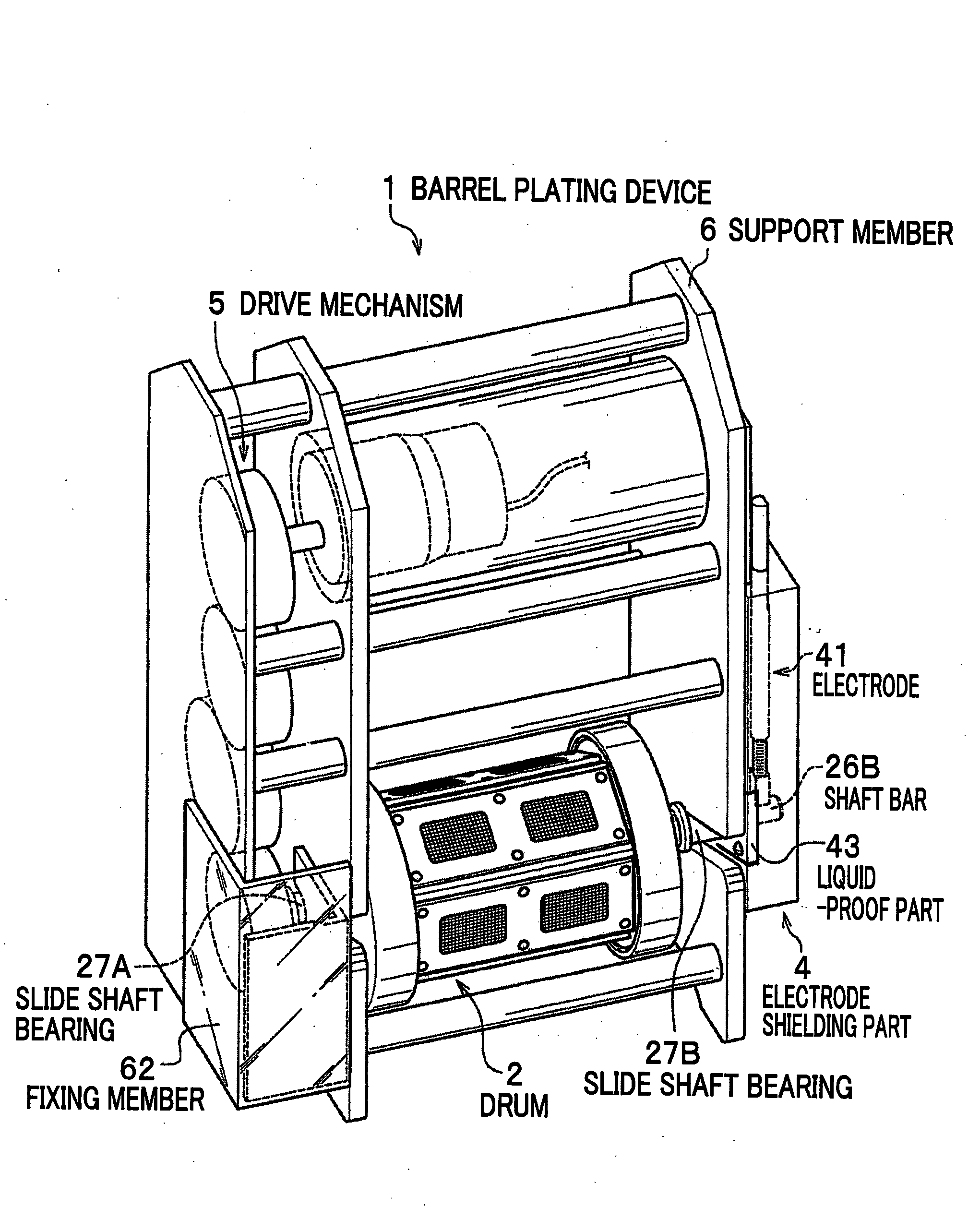
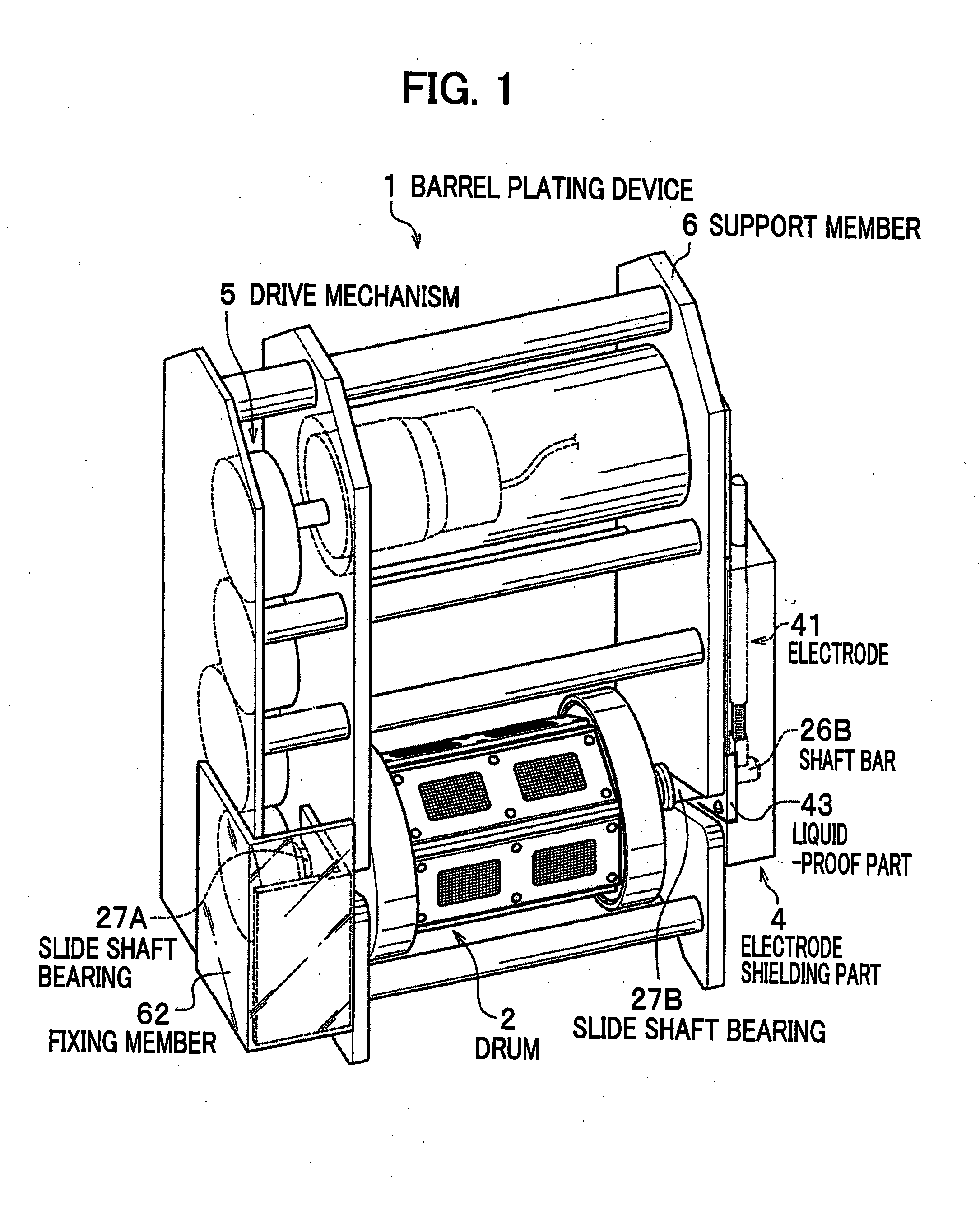
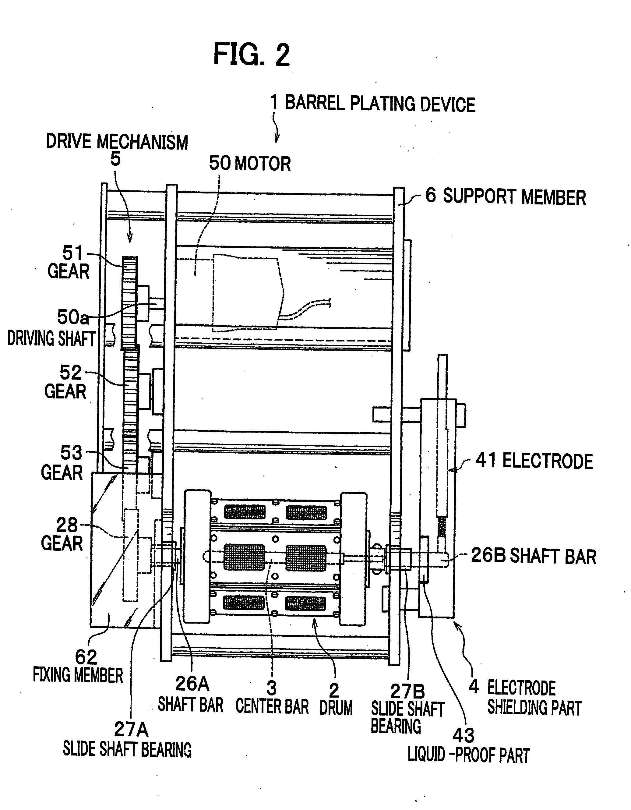
[0043]A barrel plating device 1 according to the present invention is a device for plating small objects, such as small parts, and as shown in FIGS. 1 and 2, is mainly formed of: a drum 2 configured for holding objects to be plated therein; a center bar 3 arranged in the drum 2 coaxially with the drum 2 (see FIG. 2); an electrode shielding part 4 configured for protecting an electrically connected part between a shaft bar 26B and an electrode 41 from a plating solution, to which shaft bar 26B the center bar 3 is connected; a driving mechanism 5 configured for rotatably driving the drum 2 about a center of an axle thereof; and a support member 6 configured for rotatably supporting the drum 2.

[0044]Also referring to FIG. 8, when the barrel plating device 1 is operated, it is immersed in a plating solution L contained in a plating bath 11 in which a posit...


PUM


Abstract

A barrel plating device includes a cylindrical drum which is immersed in a plating solution in a horizontal state and configured for containing objects to be plated; a support member for rotatably supporting the drum; a drive mechanism for rotatably drive the drum; and a conductive member in a shape of bar which is disposed coaxially with the drum and integrally rotate with the drum.

Description

CROSS-REFERENCE TO RELATED APPLICATIONS[0001]This application claims the foreign priority benefit under Title 35, United States Code, section 119 (a)-(d), of Japanese Patent Application No. 2006-120392, filed on Apr. 25, 2006 in the Japan Patent Office, the disclosure of which is herein incorporated by reference in its entirety.BACKGROUND OF THE INVENTION[0002]1. Field of the Invention[0003]The present invention relates to a barrel plating device suitable for plating small objects.[0004]2. Description of the Related Art[0005]As for a barrel plating device for plating small objects, there has been known a device having: a horizontally and rotatably supported drum for holding objects to be plated therein; a plating bath for storing a plating solution in which the drum is immersed; a negative electrode which is held in the drum together with the objects to be plated; and a positive electrode disposed in the plating solution in the plating bath in such a manner that a periphery of the d...

Claims


Application Information

Patent Timeline
IPC IPC(8): C25D17/00
CPCC25D17/20
Inventor YAMAMOTO, WATARUKATSUMOTO, TOKIKOHOSHINO, YOSHIAKI
Owner YAMAMOTO MS
Learn More