Vibration motor
- Summary
- Abstract
- Description
- Claims
- Application Information
AI Technical Summary
Benefits of technology
Problems solved by technology
Method used
Image
Examples
first embodiment
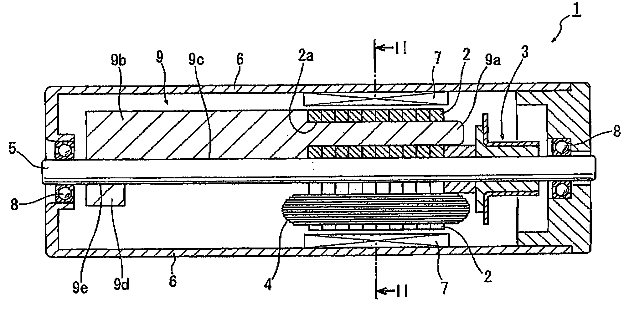
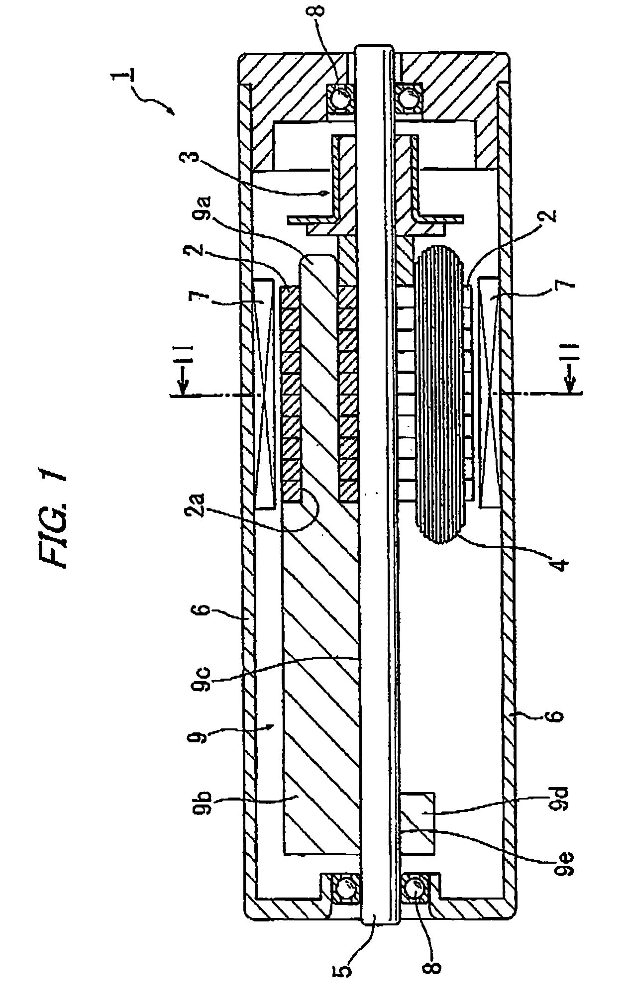
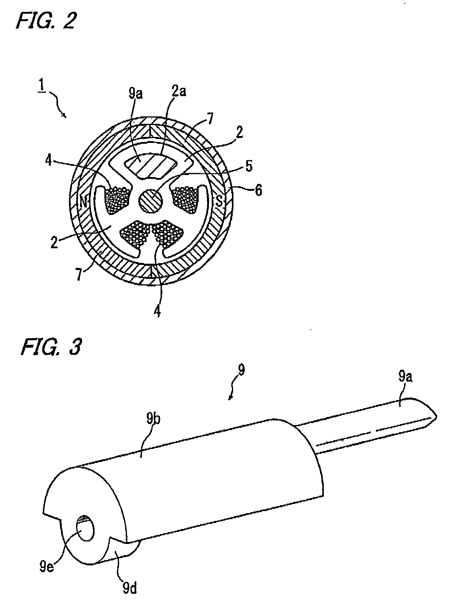
[0043]Now, referring to FIGS. 1 through 6B, description is made about a motor with a commutator as a vibration motor according to a first embodiment of the present invention.
[0044]FIG. 1 is a schematic axial cross-sectional view of the motor with a commutator (hereinafter referred to simply as “motor” as appropriate) 1 according to the first embodiment of the present invention.
[0045]FIG. 2 is a schematic radial cross-sectional view of the motor 1 shown in FIG. 1, taken from line I-I of FIG. 1.
[0046]In the motor 1, a commutator unit 3 and an armature core 2 are mounted on a rotary shaft 5thereby constituting a rotor as a whole. The rotary shaft 5 is detachably disposed and rotatably supported via bearings 8 attached to a frame 6. Magnets 7 are attached to the frame 6 thereby constituting a stator as a whole.
[0047]The armature core 2 is configured such that a required number of magnetic plates each having punched three salient poles are stacked on one another, and only two out of the ...
second embodiment
[0056]Next, referring to FIGS. 7 through 9, description proceeds to a motor with a commutator as a vibration motor according to a second embodiment of the present invention.
[0057]FIG. 7 is a schematic axial cross-sectional view of the motor with a commutator 101 according to the second embodiment of the present invention.
[0058]In the second embodiment, components similar to those of the first embodiment are designated by like reference numerals and their detailed descriptions are omitted accordingly.
[0059]According to the second embodiment, a weight 109 serving as an eccentric weight to vibrate the motor 101 is secured to the rotary shaft 5 not by itself but by means of a weight holding member 112 provided separately from the weight 109.
[0060]FIG. 8 is a perspective view of the weight 109 shown in FIG. 7 seen from above, and FIG. 9 is a perspective view of the weight holding member 112 shown in FIG. 7 seen from below.
[0061]Referring to FIG. 8, the weight 109 includes a semi-cylindri...
third embodiment
[0074]Next, referring to FIGS. 10 through 12, description proceeds to a motor with a commutator as a vibration motor according to a third embodiment of the present invention.
[0075]FIG. 10 is a schematic axial cross-sectional view of the motor with a commutator according to the third embodiment of the present invention.
[0076]In the third embodiment, components similar to those of the first embodiment are designated by like reference numerals and their detailed descriptions are omitted accordingly.
[0077]According to the third embodiment, a weight 209 serving as an eccentric weight to vibrate a motor 201 is secured to the rotary shaft 5 not by itself but by means of a weight holding member 212 provided separately from the weight 209.
[0078]FIG. 11 is a perspective view of the weight 209 shown in FIG. 10 seen from above, and FIG. 12 is a perspective view of the weight holding member 212 shown in FIG. 10 seen from below.
[0079]A material for the weight 209 is determined by giving priority ...
PUM
 Abstract
Description
Claims
Application Information
 - R&D
- Intellectual Property
- Life Sciences
- Materials
- Tech Scout
- Unparalleled Data Quality
- Higher Quality Content
- 60% Fewer Hallucinations
Browse by: Latest US Patents, China's latest patents, Technical Efficacy Thesaurus, Application Domain, Technology Topic, Popular Technical Reports.
© 2025 PatSnap. All rights reserved.Legal|Privacy policy|Modern Slavery Act Transparency Statement|Sitemap|About US| Contact US: help@patsnap.com


