Calorimeter

Active Publication Date: 2007-10-18
LECO CORPORATION
View PDF31 Cites 6 Cited by
  • Summary
  • Abstract
  • Description
  • Claims
  • Application Information

AI Technical Summary

Benefits of technology

[0013] In accordance with the present invention, an improved apparatus and method has been developed for determining the calorific value of combustible substances. The apparatus employs a cover, which can be used to partition a single isothermal reservoir into an outer jacket and an internal bucket for receiving the calorimeter vessel. The apparatus improves the thermal isolation between the combustion vessel and the surrounding environment to achieve more accurate results.
[0017] In one embodiment also, the bucket cover includes a lower section with a quick disconnect coupling cooperating with the combustion vessel cover to minimize the thermal communication between the bucket cover and combustion vessel.

Problems solved by technology

In the past, somewhat complicated apparatus has been employed for the determination of the calorific value of solid and liquid substances in accordance with standard methodology (ASTM / ISO standards).
One disadvantage of using separate reservoirs in a calorimeter is that, during routine operation, the systems require an external source of coolant water to eliminate thermal energy generated by the combustion of the sample.
Also, the use of multiple reservoirs in such prior art systems requires numerous valves and conduits with which to direct the water to and from the reservoirs.
The operation of prior art isothermal calorimeters is further complicated by the requirement to maintain the temperature of the water substantially constant in all reservoirs from one analysis to the next.

Method used


Image

  • Calorimeter
  • Calorimeter
  • Calorimeter

Examples


Embodiment Construction

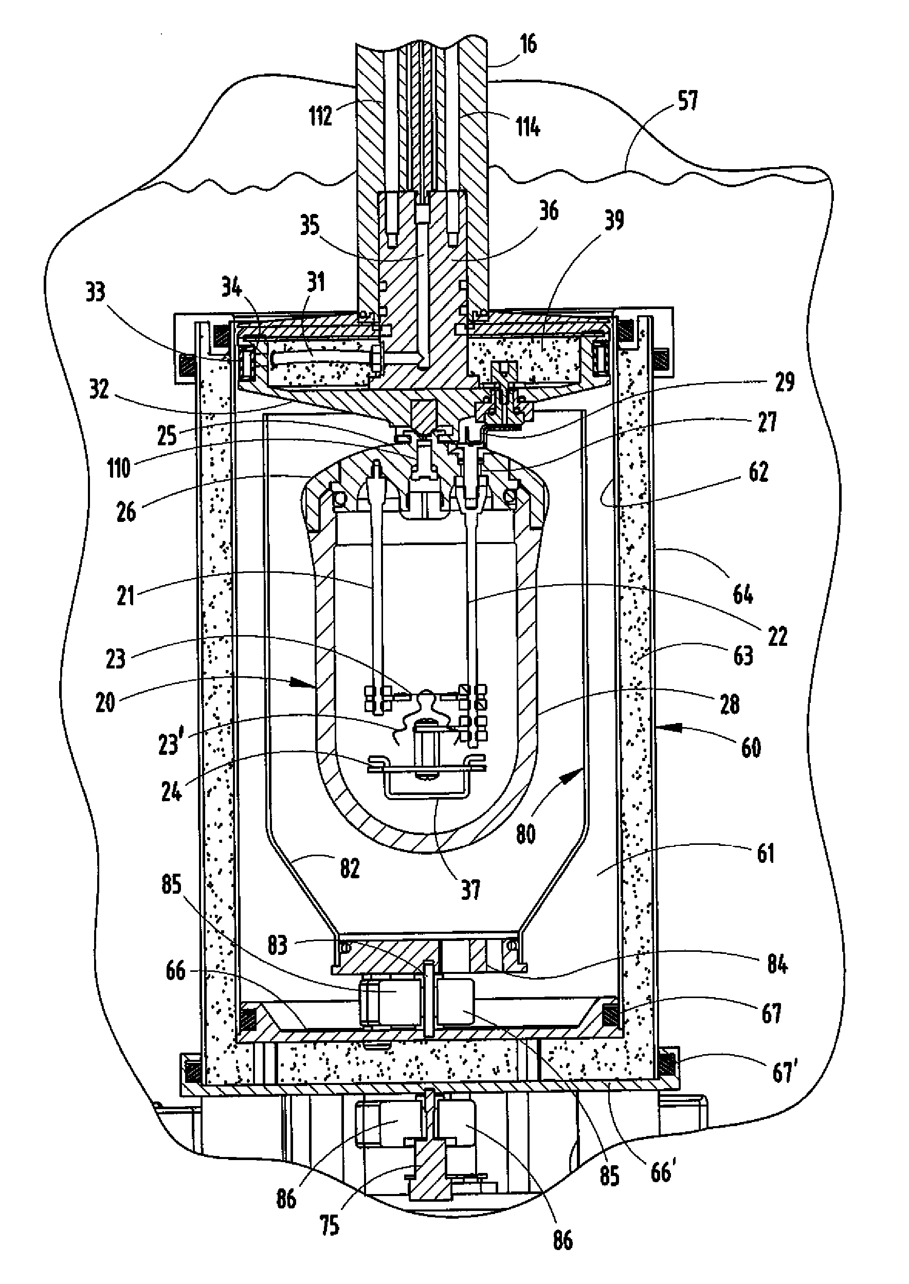
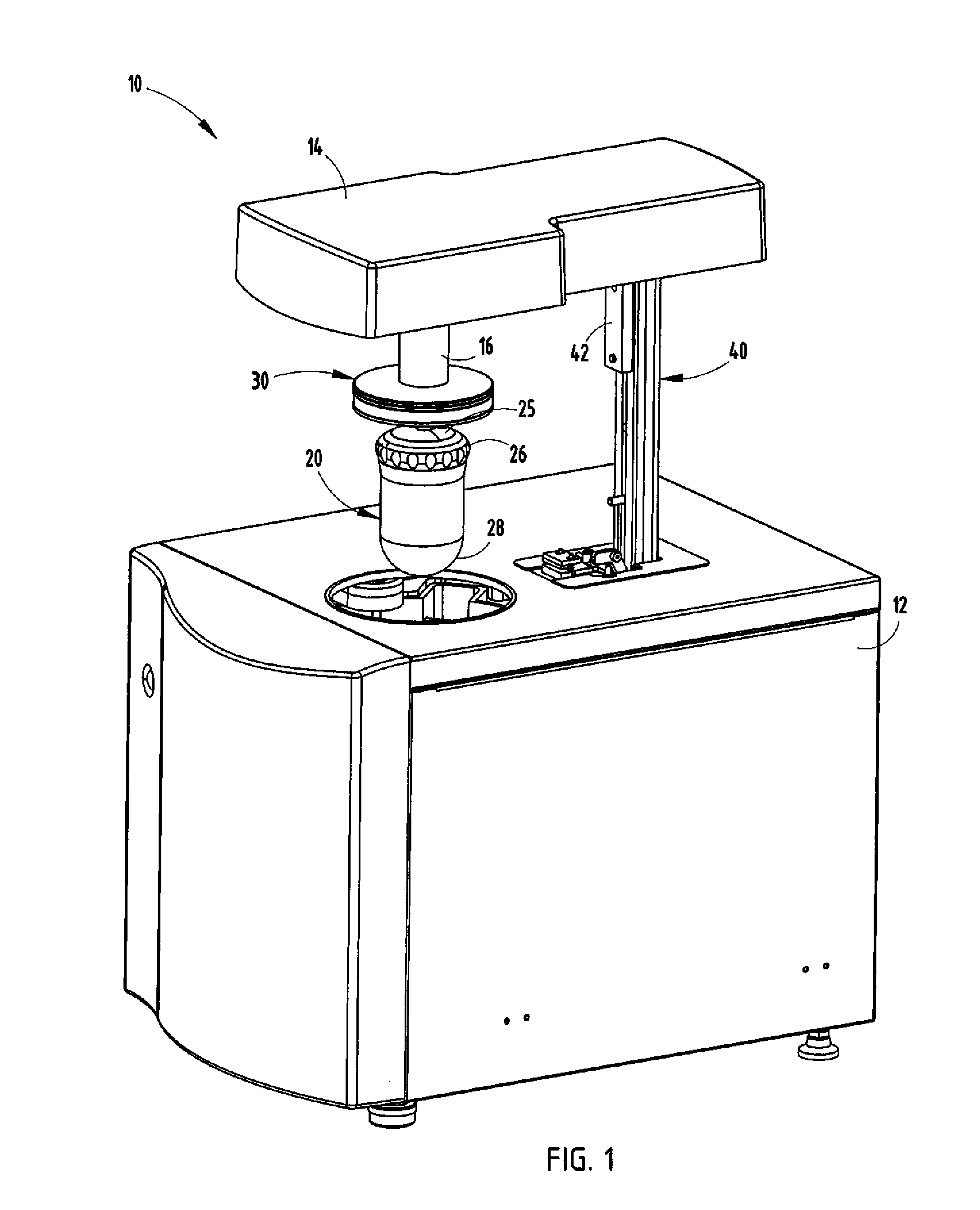
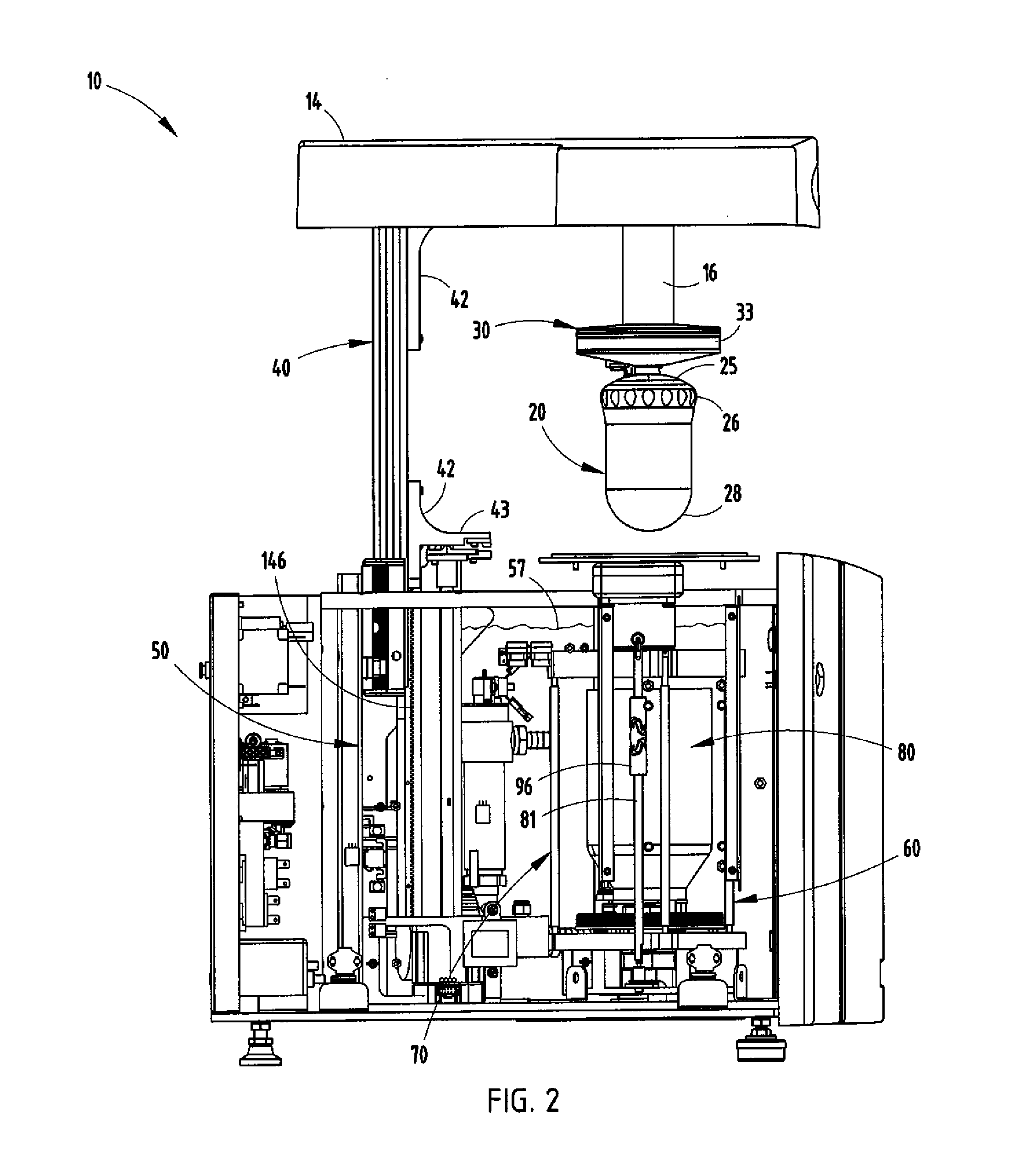
[0032] Referring initially to FIGS. 1-4, there is shown a calorimeter 10 embodying the present invention. The calorimeter is shown in FIGS. 1, 2, and 4 in an open position for loading and removal of the combustion vessel 20 for introducing a sample, installing the ignition fuse, and filling the vessel with combustion oxygen. In FIG. 3, the calorimeter is shown in a closed position with the combustion vessel 20 immersed in an isothermal reservoir during an analysis. The calorimeter combustion vessel 20 is made of stainless steel about 0.25 inches thick with a top 25 sealably engaging the bullet-shaped curved blunt enclosed lower end 28 and is retained by a threaded closure ring 26.

[0033] Calorimeter 10 includes a cabinet 12, as seen in FIG. 1, enclosing frame members which support the components of the calorimeter, including the fluid connections as illustrated in FIG. 9 and described below. Cabinet 12 also houses the internal components of the calorimeter as well as electrical comp...


PUM


Abstract

A calorimeter includes a bucket cover which is used to reconfigure an isothermal water reservoir to provide for temperature equilibration prior to sample analysis and subsequently define a fixed volume of water during analysis in which high precision temperature measurements can be recorded. The apparatus includes mechanisms for sealing and controlling the cover, and for coupling the combustion vessel to the cover while minimizing the thermal contact between them. Improved thermal isolation between the fixed volume of water and the surrounding environment is also achieved.

Description

CROSS-REFERENCE TO RELATED APPLICATIONS [0001] This application is a continuation-in-part of U.S. patent application Ser. No. 11 / 416,970 filed on May 3, 2006, entitled CALORIMETER, the entire disclosure of which is incorporated herein by reference.BACKGROUND OF THE INVENTION [0002] The present invention relates to a calorimeter including a combustion vessel and an integrated isothermal fluid reservoir. [0003] In the past, somewhat complicated apparatus has been employed for the determination of the calorific value of solid and liquid substances in accordance with standard methodology (ASTM / ISO standards). The operation of such an apparatus is well understood and has been described in, for example, the American National Standard Institute ANSI / ASTM D5865. [0004] Prior calorimeters have required the use of multiple internal and external reservoirs with which to contain and manage the water required to operate the apparatus. U.S Pat. Nos. 4,398,836 and 4,616,938 disclose calorimeters w...

Claims


Application Information

Patent Timeline
IPC IPC(8): G01N25/22
CPCG01K17/00Y10T436/208339G01N25/4866G01N25/44
Inventor BRUSHWYLER, KEVIN R.HOSS, JOHN T.LATINO, OCTAVIO R.
Owner LECO CORPORATION
Why Eureka
Try Eureka