
Steering tool

a technology of steering tool and guiding rod, which is applied in the direction of drilling pipe, directional drilling, borehole/well accessories, etc., can solve the problems of increased drag and torque on drilling string, failure of drilling string and production problems, and only possible steering

Active Publication Date: 2007-10-11
HALLIBURTON ENERGY SERVICES INC
View PDF60 Cites 41 Cited by
  • Summary
  • Abstract
  • Description
  • Claims
  • Application Information

AI Technical Summary

Benefits of technology

[0058]The actuating levers are comprised of a pivot point so that the actuating levers pivot about the pivot point in response to the actuating movement of the tool actuating device. Preferably the actuating levers are substantially balanced about the pivot point so that centrifugal force generated during rotation of the steering tool does not tend to cause the actuating levers to pivot.
[0133]In addition, inadvertent actuation of the steering devices to the extended position during rotation of the drill string in the preferred embodiments may be minimized by ensuring that the mechanical valve actuators are in the second actuator position for less time during one rotation of the drill string than they are in the first actuator position during one rotation of the drill string. This may be achieved by providing that the mechanical valve actuators are moved to the first position for less than 180 degrees during one rotation of the drill string. This in turn may be achieved by providing that each of the mechanical valve actuators extends circumferentially around the housing less than 180 degrees.

Problems solved by technology

The resulting borehole may exhibit crookedness or spiralling, may include doglegs and / or keyseats and may cause increased drag and torque on the drilling string, drilling string failures and production problems.
One disadvantage to this first option is that steering is only possible in the sliding drilling mode.
A second disadvantage to this first option is that the straightness of the borehole in rotary drilling mode may be compromised by the presence of the bent drilling motor.
One disadvantage to rotary steerable drilling systems is that they tend to be relatively expensive and relatively complex apparatus, due in part to the necessity of determining orientations and directions in three dimensions for directional drilling applications.
In operation, deviation of the drilling string from vertical results in similar deviation of the oscillating pendulum.
In operation, deviation of the drilling string from a desired orientation is sensed by the inclinometers and results in activation of the hydraulic pumps.

Method used


Image

  • Steering tool
  • Steering tool
  • Steering tool

Examples


Embodiment Construction

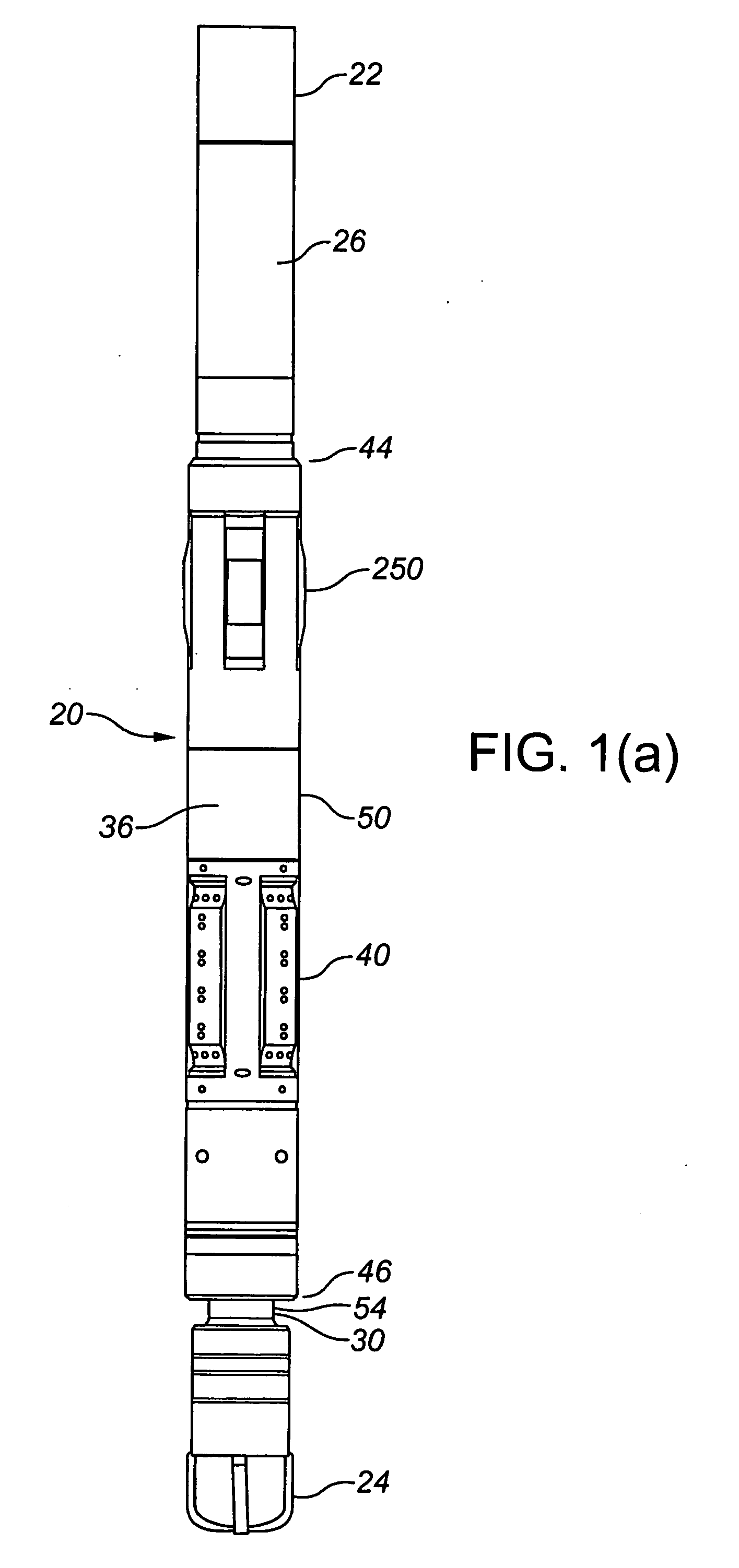
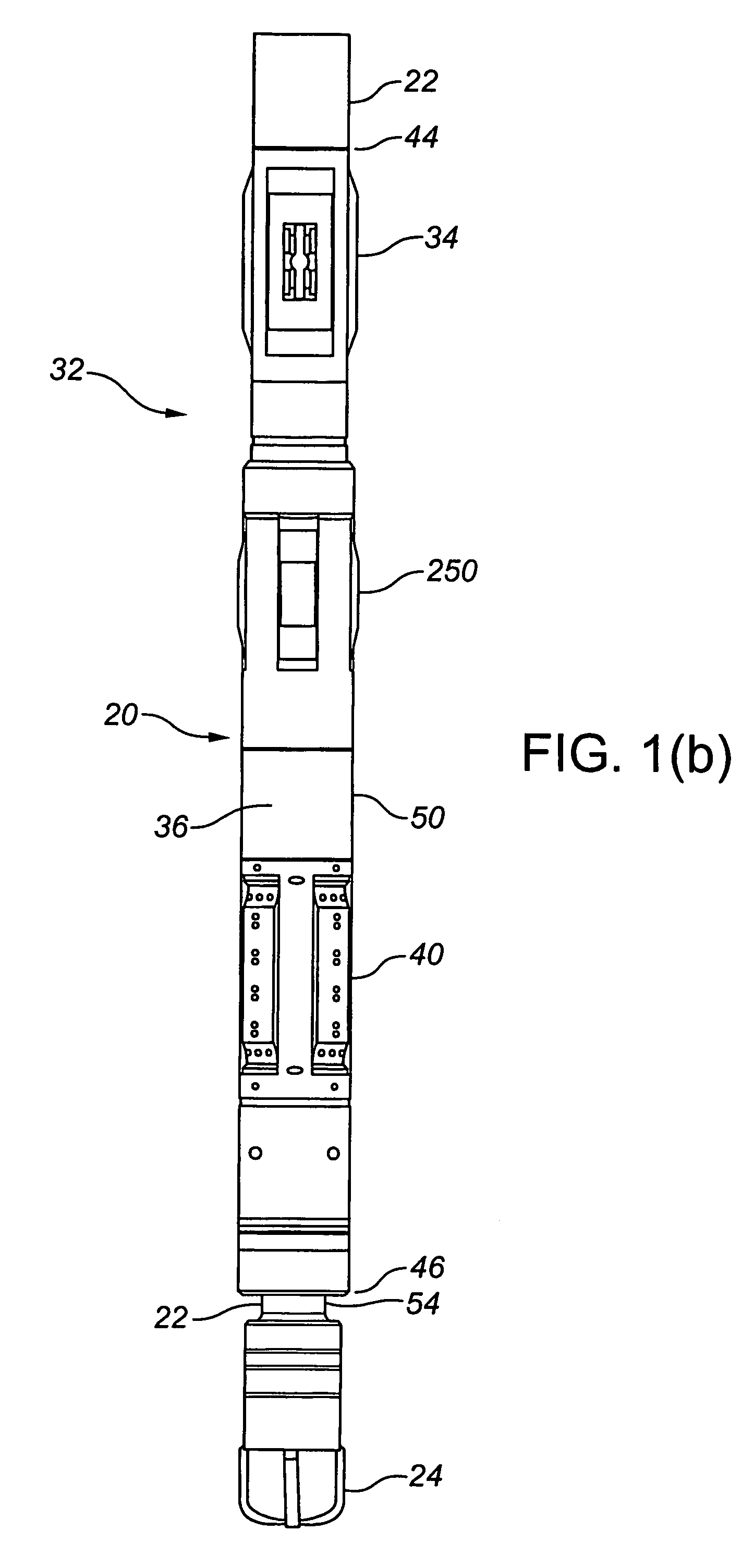
[0160]Referring to FIG. 1, a steering tool (20) according to the invention is depicted in three different exemplary configurations incorporated within a drill string (22). In all three exemplary configurations, a drill bit (24) is located at a distal end of the drill string (22).

[0161]In FIG. 1(a), the steering tool (20) is configured as a component of a drilling motor (26) having a motor housing (28) and a motor drive shaft (30). This configuration is described in detail below as a preferred embodiment of the invention.

[0162]In FIG. 1(b), the steering tool (20) is configured as a component of a rotary steerable drilling system (32) of the type in which a steering mechanism is rotatably connected with the drill string (22). In this configuration, the drill string (22) extends through the steering tool (20) and the steering tool (20) includes a borehole engaging device (34) for inhibiting the steering tool (20) from rotating in a borehole (not shown) when the drill string (22) is rot...


PUM


Abstract

A steering tool for use in drilling a borehole, including a tubular housing, a tool actuating device movably supported within the housing, a plurality of hydraulically actuated steering devices circumferentially spaced about the housing, and a hydraulic control system interposed between the tool actuating device and the steering devices for converting an actuating movement of the tool actuating device to independent actuation of the steering devices.

Description

TECHNICAL FIELD[0001]A steering tool for use in drilling a borehole.BACKGROUND OF THE INVENTION[0002]In vertical drilling, a typical objective is to drill a consistently vertical borehole in a manner which minimizes the number and magnitude of unintended deviations of the borehole from vertical. In directional drilling, a typical objective is to drill a borehole along a predetermined path or paths to reach a subsurface target in a manner which minimizes the number and magnitude of unintended deviations and other unintended directional changes of the borehole.[0003]In either case it is desirable to have the ability to control the drilling direction while drilling, since the existence of unintended directional changes complicates both drilling and completion and can increase the amount of time required to drill and complete the borehole.[0004]Unintended directional changes in a borehole may be due to such causes as the characteristics of the formation being drilled, the characteristic...

Claims


Application Information

Patent Timeline
Patent Type & Authority Applications(United States)
IPC IPC(8): E21B7/08
CPCE21B7/062E21B7/10E21B7/068
Inventor KIRKHOPE, KENNEDYRIEDER, PAULYUNG, LISAHAY, RICHARD T.CRASE, GARY M.
Owner HALLIBURTON ENERGY SERVICES INC
Learn More