
Register for air conditioning

a register and air conditioning technology, applied in vehicle components, vehicle heating/cooling devices, transportation and packaging, etc., can solve the problems of large pressure loss, inability to control the blowing direction of air-conditioning air, and large noise, so as to achieve high accuracy, enlarged pressure loss, and loud noise

Inactive Publication Date: 2007-10-04
TOYODA GOSEI CO LTD
View PDF54 Cites 19 Cited by
  • Summary
  • Abstract
  • Description
  • Claims
  • Application Information

AI Technical Summary

Benefits of technology

[0010]The present invention has been developed in view of the aforementioned circumstances. It is therefore an object of the present invention to provide an air-conditioning register which can inhibit the enlargement of pressure loss; can reduce noises; and can control the blowing direction of air-conditioning air with high accuracy.

Problems solved by technology

When the conventional air-conditioning register exhibits an excessively small clearance “W,” it produces a large pressure loss, and air-conditioning air, which flows through such an excessively small clearance “W,” produces loud noises.
On the other hand, when the conventional air-conditioning register exhibits an excessively large clearance “W.” it cannot control the blowing direction of air-conditioning air, which flows through such an excessively large clearance “W,” with high accuracy.
Moreover, the conventional air-conditioning register illustrated in FIG. 7 might suffer from a problem that it cannot control the blowing direction of air-conditioning air downward with high accuracy because the neighboring fins 401 overlap in less overlapping magnitude in the blowing direction of air-conditioning air.
However, such elongated fins 401 have closed the flow passage for air-conditioning air virtually to increase the pressure loss more.
However, the conventional register with a reduced quantity of elongated fins 401 has exhibited an excessively large clearance “W” when directing the elongated fins 401 in directions other than downward so that it cannot control the blowing direction of air-conditioning air with high accuracy in directions other than downward.

Method used


Image

  • Register for air conditioning
  • Register for air conditioning
  • Register for air conditioning

Examples


example

[0046]An air-conditioning register according to a specific example of the present invention will be hereinafter described in detail with reference to the accompanying drawings.

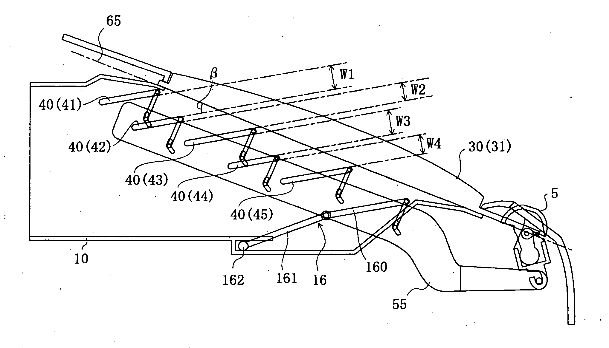
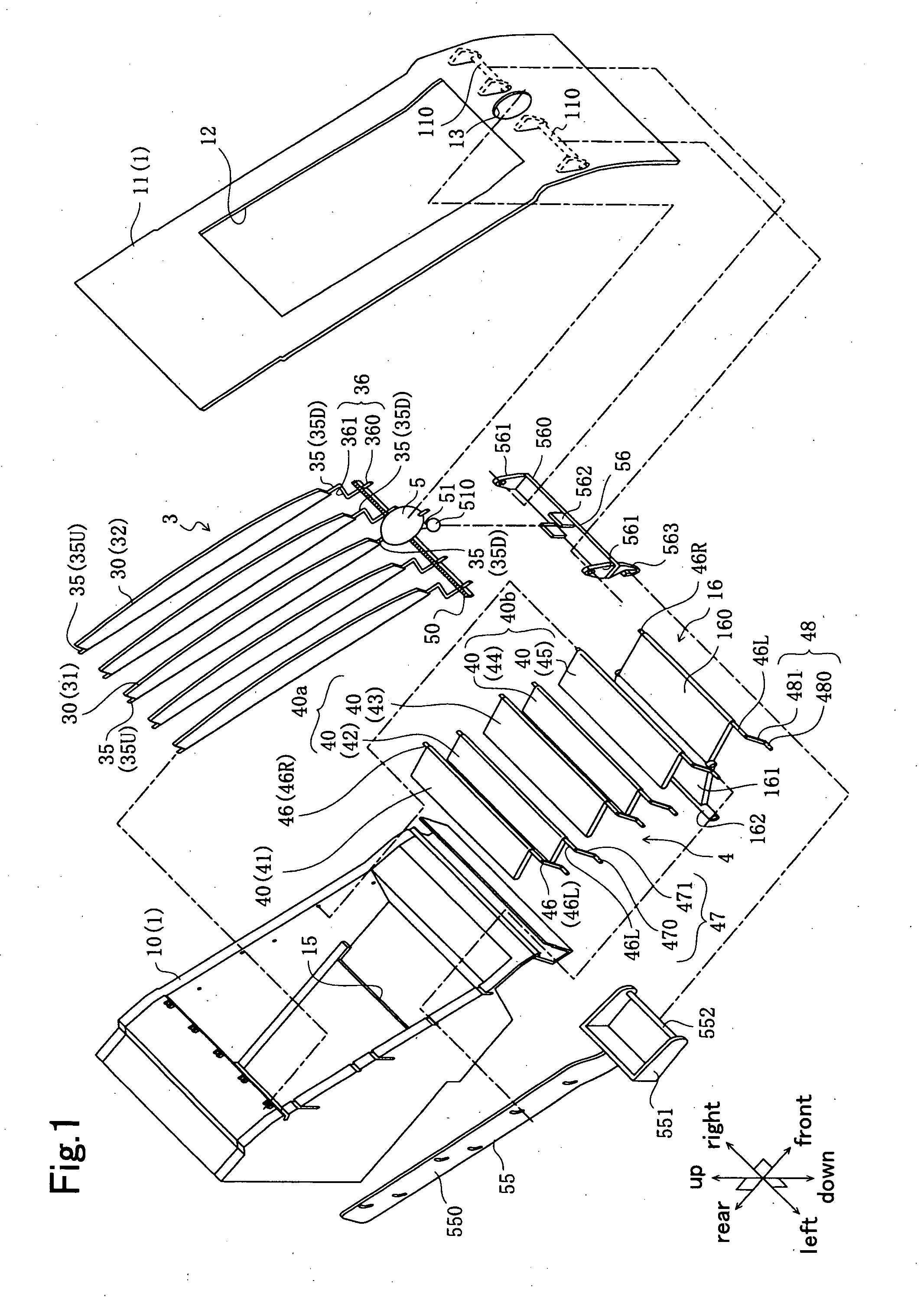
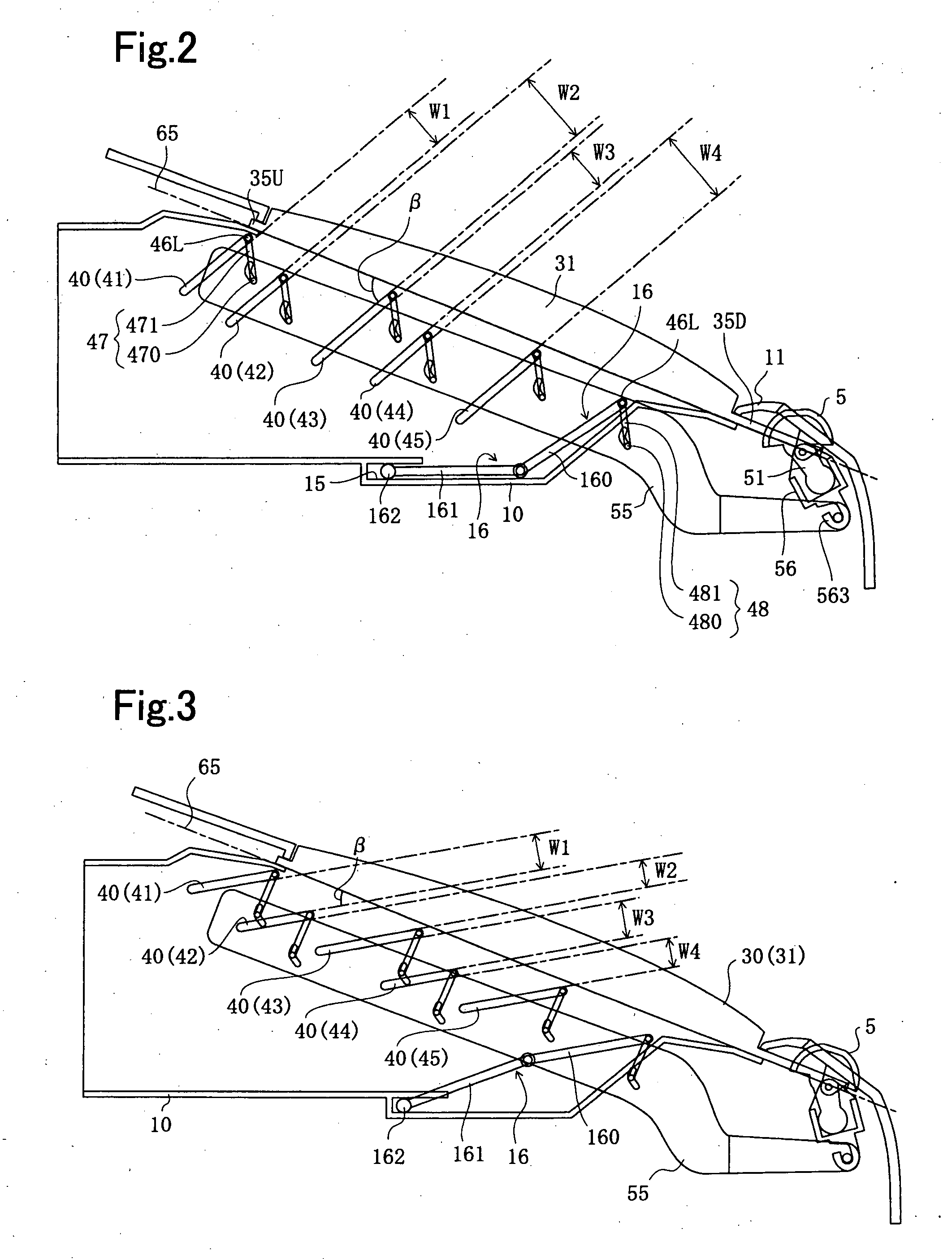
[0047]For example, an air-conditioning register according to an example of the present invention is disposed along with a monitor (not shown in the drawings) for car navigation system in an automobile instrument panel. Specifically, FIG. 1 schematically illustrates the air-conditioning register according to Example of the present invention in an exploded perspective view. FIGS. 2 through 5 illustrate the operations of the air-conditioning register according to Example in an explanatory diagram, respectively. Note that FIGS. 2 through 5 show the air-conditioning register according to Example, which is viewed on the left side thereof. In the following descriptions on the air-conditioning register according to Example, the terms, “up,”“down,”“right,”“left,”“front” and “rear,” specify those “up,”“down,”“right,”“le...


PUM


Abstract

An air-conditioning register includes a cylinder-shaped retainer, and a fin assembly, which includes a plurality of synchronously swingable fins. The fin assembly includes a fin sub-assembly. The fin sub-assembly includes the fins, which neighbor to each other, in a quantity of from two or more to less than a total number of the fins. The fins, which belong to an identical fin sub-assembly, make a first imaginary plane, which passes the swing shafts of the fins. The fins, which neighbor to each other but are free of belonging to the identical fin sub-assembly, make a second imaginary plane, which passes the swing shafts of the fins. The first imaginary plane and the second imaginary plane cross to each other. The fins, which belong to the identical fin sub-assembly, are disposed one after another consecutively when the fins swing to a predetermined position, respectively.

Description

BACKGROUND OF THE INVENTION[0001]1. Field of the Invention[0002]The present invention relates to a register for air conditioning, register which is connected with air conditioner to control the blowing direction of air-conditioning air flowing toward the inside of rooms, such as vehicle passenger rooms.[0003]2. Description of the Related Art[0004]An instrument panel of automobile is provided with such a register as disclosed in Japanese Unexamined Patent Publication (KOKAI) Gazette No. 11-139,156, for instance. A register blows out air-conditioning air, which an air-conditioner produces, and controls the blowing direction of air-conditioning air.[0005]FIG. 6 illustrates one of conventional registers for air conditioning. As shown in the drawing, a conventional register comprises a retainer 100, and a fin assembly 400. The retainer 100 is formed as a cylinder shape, and demarcates a flow passage for air-conditioning air and an outlet opening 120 therefor. The fin assembly 400 compris...

Claims


Application Information

Patent Timeline
IPC IPC(8): B60H1/34
CPCB60H2001/3471B60H1/3421
Inventor SHIBATA, MINORU
Owner TOYODA GOSEI CO LTD
Learn More