Armored fiber optic cable having a centering element and methods of making

a technology of centering element and fiber optic cable, which is applied in the direction of optics, fiber mechanical structures, instruments, etc., can solve the problems of reducing affecting the production of smoke from the cable, and affecting the performance of the optical fiber, so as to prevent the strain placed on the optical fiber(s), the optical performance of at least one optical waveguide is preserved

Inactive Publication Date: 2007-10-04
CORNING CABLE SYST LLC
View PDF15 Cites 4 Cited by
  • Summary
  • Abstract
  • Description
  • Claims
  • Application Information

AI Technical Summary

Benefits of technology

[0006] One aspect of the present invention is directed to an armored fiber optic cable having a fiber optic cable having at least one optical waveguide and a cable jacket and an armor layer generally surrounds the fiber optic cable with a centering element therebetween. The cable jacket has an outer diameter and armored layer has an inner surface, wherein a gap exists between the outer diameter of the cable jacket and the inner surface of the armor layer. The centering element is disposed in the gap between the fiber optic cable and the armor layer for inhibiting the fiber optic cable from moving away from a middle of the armored fiber optic cable towards the inner surface of the armor layer during winding of the armored fiber optic cable. Consequently, the optical performance of the at least one optical waveguide is preserved by inhibiting the strain placed on the optical fiber(s) during manufacturing.

Problems solved by technology

Similarly, outdoor applications expose fiber optic cables to environmental effects such as temperature variations and / or water.
Generally speaking, an armor layer inhibits open flames from directly reaching the fiber optic cable and may delay the production of smoke from the cable when exposed to open flames if the armor layer is the outside layer.
However, manufacturing fiber optic cables with an armored layer can present certain challenges for preserving optical performance.
But using relatively high processing tensions can cause other problems during manufacturing.

Method used


Image

  • Armored fiber optic cable having a centering element and methods of making
  • Armored fiber optic cable having a centering element and methods of making
  • Armored fiber optic cable having a centering element and methods of making

Examples


Embodiment Construction

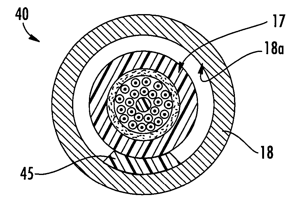
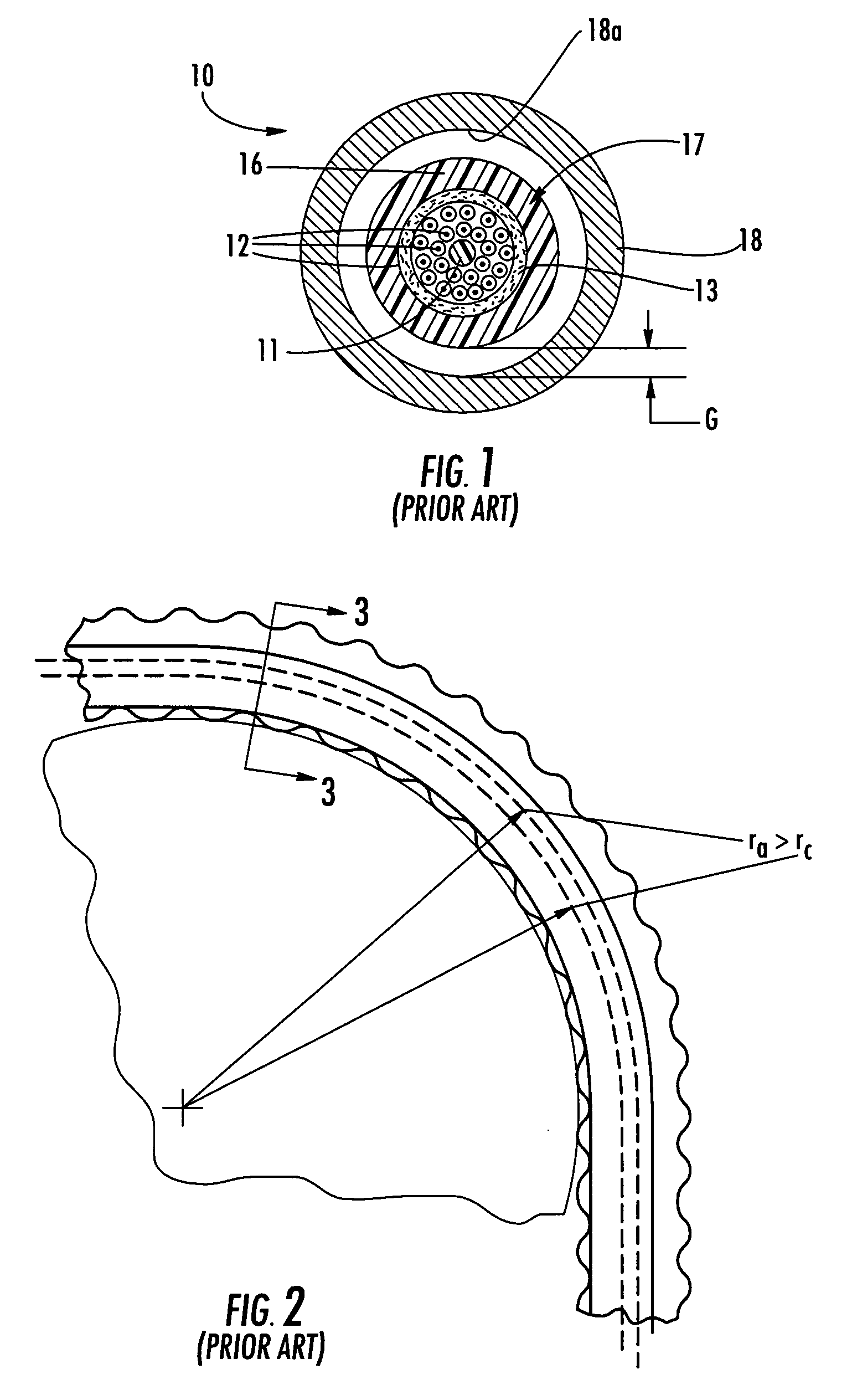
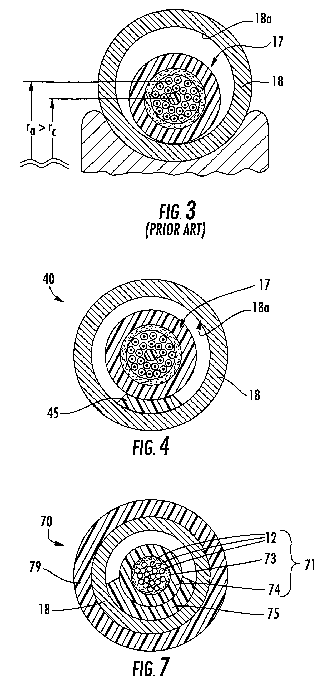
[0018] Reference will now be made in detail to the present preferred embodiments of the invention, examples of which are illustrated in the accompanying drawings. Whenever possible, the same reference numerals will be used throughout the drawings to refer to the same or like parts. FIG. 1 depicts a perspective view of a conventional armored fiber optic cable 10 (hereinafter armored cable 10) having a fiber optic cable 17 and an interlocking armor layer 18 therearound for providing additional protection to fiber optic cable 17. Fiber optic cable 17 includes a central strength member 11 having a plurality of optical waveguides such as optical fibers 12 having a buffer layer (not numbered) stranded therearound, a plurality of strength elements 13, and a cable jacket 16. As shown, a gap G exists between an outer diameter (not numbered) of the cable jacket 16 and an inner surface 18a of the interlocking armor layer 18. Using gap G between fiber optic cable 17 and interlocking armor layer...


PUM


Abstract

Armored fiber optic cables and methods for making are disclosed that include an armor layer generally surrounding a fiber optic cable that includes at least one optical waveguide and a cable jacket. The cable jacket has an outer diameter and armor layer has an inner surface, wherein a gap exists between the outer diameter of the cable jacket and the inner surface of the armor layer. The armored fiber optic cable further includes a centering element disposed in the gap between the fiber optic cable and the armor layer. The centering element generally inhibits the fiber optic cable from moving away from a middle of the armored fiber optic cable towards the inner surface of the armor layer during winding of the armored fiber optic cable, thereby inhibiting wavy armor and/or preserving the optical performance of the at least one optical waveguide.

Description

FIELD OF THE INVENTION [0001] The present invention relates generally to an armored fiber optic cable and methods for making the same. More particularly, the present invention relates to armored fiber optic cables having a centering element for keeping the cable in the middle of the armor during manufacturing. BACKGROUND OF THE INVENTION [0002] Communication networks are used to transport a variety of signals such as voice, video, data transmission, and the like. As communication applications required greater bandwidth, communication networks switched to cables having optical fibers since they are capable of transmitting an extremely large amount of bandwidth compared with a copper conductor. Moreover, a fiber optic cable is much lighter and smaller compared with a copper cable having the same bandwidth capacity. [0003] Consequently, fiber optic cables are used in a wide variety of applications and must meet specific criteria for the given application while preserving optical perfor...

Claims


Application Information

Patent Timeline
Patent Type & Authority Applications(United States)
IPC IPC(8): G02B6/44
CPCG02B6/4488
Inventor MCALPINE, WARREN W.MCDOWELL, SCOTT A.BURNS, RODNEY M. JR.REGISTER, JAMES A. III
Owner CORNING CABLE SYST LLC
Why Eureka
Try Eureka