
Method for tracing a program executed on a system comprising a plurality of processing units, and a system comprising a plurality of processing units

a technology of processing units and programs, applied in the field of methods for tracing programs executed on systems comprising a plurality of processing units, can solve problems such as the increase of access overhead, and achieve the effect of reducing the load on the bus between nodes

Inactive Publication Date: 2007-09-27
FUJITSU LTD
View PDF1 Cites 6 Cited by
  • Summary
  • Abstract
  • Description
  • Claims
  • Application Information

AI Technical Summary

Benefits of technology

[0010] An object of the present invention is to provide a trace method, which can reduce a load on a bus between nodes when the operations of an operating system or a program are traced in an NUMA system, for a program executed in the NUMA system, and to provide an NUMA system.
[0011] Another object of the present invention is to provide a trace method, which can continue to reduce a load on a bus between nodes even if a task is transferred when the operations of an operating system or a program are traced in an NUMA system, for a program executed in the NUMA system, and to provide an NUMA system.
[0013] Here, the task control block is generated based on the tracer storage destination / trace information output destination storage area, which makes a correspondence between the storage destination of the tracer and the output destination of the trace information in the primary storage area for each processing unit. Each processing unit sets the storage destination of the tracer and the output destination of the trace information in a memory module of the node of the processing unit itself, makes specification to output the trace information to the trace information output destination area specified in the task control block when executing the trace process, and executes the tracer specified in the task control block, whereby an access between the nodes, which occurs with the execution of the trace, can be prevented from arising, and a load on the bus between the nodes can be reduced.
[0015] Here, the task control block is generated based on the tracer storage destination / trace information output destination storage area, which makes a correspondence between the storage destination of the tracer and the output destination of the trace information in the primary storage area for each processing unit. Each processing unit sets the storage destination of the tracer and the output destination of the trace information in a memory module of the node of the processing unit itself, and at the same time, the transfer source processing unit that is responsible for a task rewrites a responsible processing unit to the transfer destination processing unit for the corresponding task control block, and also rewrites the storage destination of the tracer and the output destination of the trace information to a storage destination and an output destination, which correspond to the transfer destination processing unit, when the transfer of the task corresponding to the program is determined, whereby an access between the nodes, which occurs with the execution of the trace, can be prevented from arising, and a load on the bus between the nodes can continue to be reduced even after the task is transferred.
[0018] According to the present invention, a load on a bus between nodes can be reduced when the operations of an operating system or a program are traced in an NUMA system.

Problems solved by technology

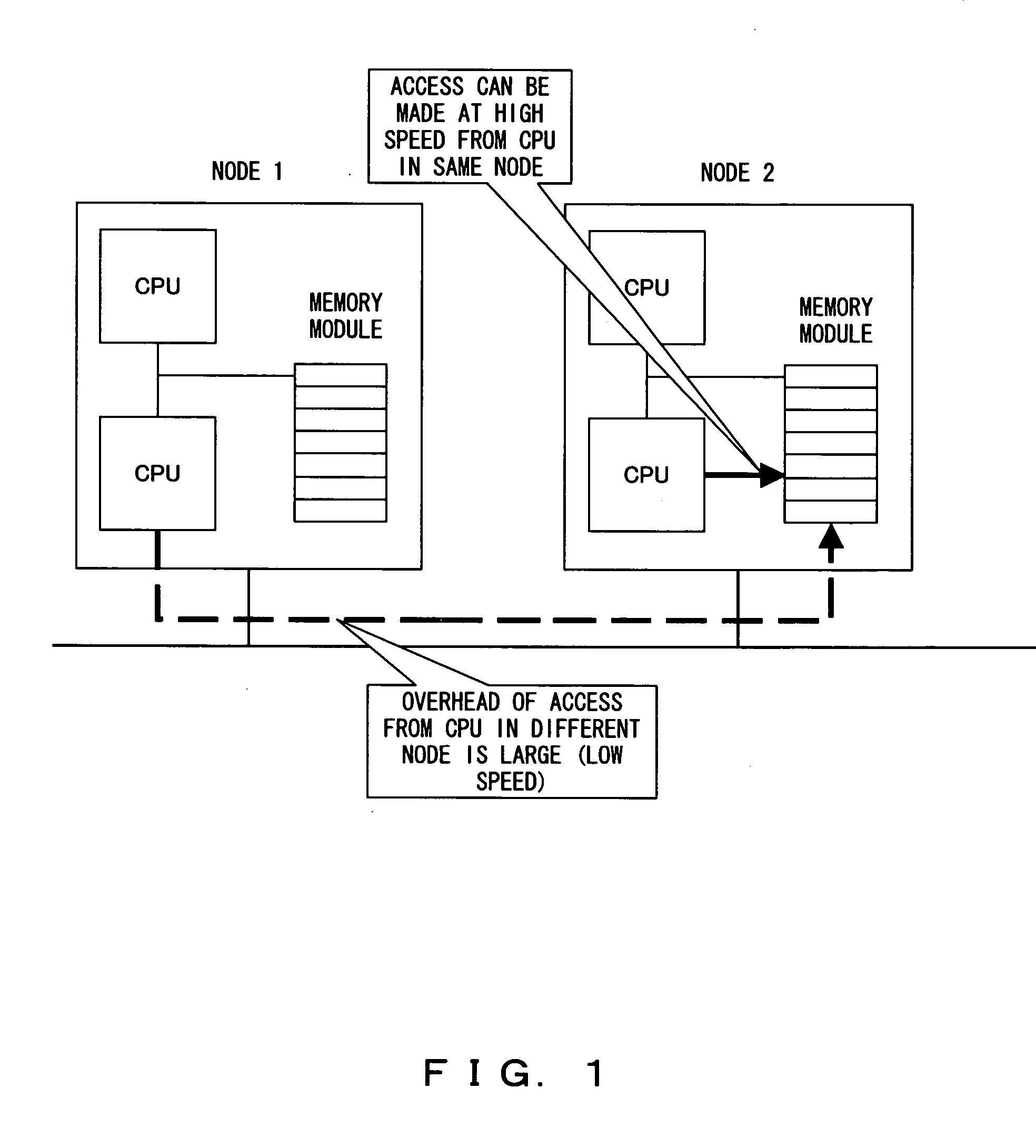
For example, as shown in FIG. 1, if a node of a CPU which is executing a trace process is different from that of a memory module where the area for storing trace information is secured, a memory access between the nodes must be made, leading to an increase in the overhead of the access.

Method used


Image

  • Method for tracing a program executed on a system comprising a plurality of processing units, and a system comprising a plurality of processing units
  • Method for tracing a program executed on a system comprising a plurality of processing units, and a system comprising a plurality of processing units
  • Method for tracing a program executed on a system comprising a plurality of processing units, and a system comprising a plurality of processing units

Examples


Embodiment Construction

[0031] Preferred embodiments according to the present invention are hereinafter described in detail with reference to the drawings.

[0032] An NUMA system is a system that can comprise a plurality of nodes. Namely, the NUMA system is configured by one or more nodes. Each of the nodes is configured by mounting one or more CPUs on a board along with a memory module.

[0033]FIG. 2 is a diagram showing the configuration of an NUMA system according to a preferred embodiment of the present invention.

[0034] In this figure, nodes 11 and 15, each of which is configured by mounting two CPUs on a board along with a memory module, are interconnected by a bus 19.

[0035] Namely, the node 11 is configured by the CPUs 12 and 13 and the memory module 14, whereas the node 15 is configured by the CPUs 16 and 17 and the memory module 18.

[0036] Any of the nodes in the NUMA system, for example, the node 11 is determined as a node where a BOOT CPU to be described later exists. In the memory module 14 of t...


PUM


Abstract

In a method for tracing a program according to the present invention, a processing unit that executes a program, generates a task control block corresponding to the program based on a tracer storage destination / trace information output destination storage area, which makes a correspondence between the storage destination of a tracer and the output destination of trace information in a primary storage area for each of the plurality of processing units, specifies to output the trace information to a trace information output destination area specified in the task control block when executing the trace process, and executes the tracer specified in the task control block.

Description

BACKGROUND OF THE INVENTION [0001] 1. Field of the Invention [0002] The present invention relates to a method for tracing a program executed on a system comprising a plurality of processing units, and a system comprising a plurality of processing units. [0003] 2. Description of the Related Art [0004] A technique for tracing the operations of an operating system (OS), or the operations of a program running on the OS is known. By way of example, for Linux, LKST (Linux Kernel State Tracer), or LTT (Linux Trace Toolkit) is well known as a tracer of an event within a kernel of Linux. [0005] In the meantime, a system comprising a plurality of CPUs (Central Processing Units), such as an SMP (Symmetric Multiple Processor) system or an NUMA (Non Uniform Memory Access) system is known. [0006] In the NUMA system, one or more CPUs and a memory module are arranged on each node (CPU board). [0007] In the conventional NUMA system, an area for storing trace information is secured within a memory mo...

Claims


Application Information

Patent Timeline
Patent Type & Authority Applications(United States)
IPC IPC(8): G06F9/44
CPCG06F11/3636
Inventor KATO, TAKEHARU
Owner FUJITSU LTD
Learn More