
PDT apparatus with an addressable LED array for therapy and aiming

a technology of led arrays and led arrays, which is applied in the field of pdt apparatuses with an addressable led array for therapy and aiming, can solve the problems of inability to tailor light to the shape of diseased tissue, relatively expensive laser equipment used for pdt, and time-consuming process for physicians

Inactive Publication Date: 2007-09-27
LIGHT SCI ONCOLOGY
View PDF12 Cites 29 Cited by
  • Summary
  • Abstract
  • Description
  • Claims
  • Application Information

AI Technical Summary

Benefits of technology

[0007] In accordance with the present invention, the disadvantages of prior PDT systems and apparatus for treating ocular diseases have been overcome. In accordance with the present invention, the PDT apparatus includes an addressable LED array so that the size and shape of the LED light used for aiming or therapy is selectable and can be matched to the size and shape of targeted tissue.
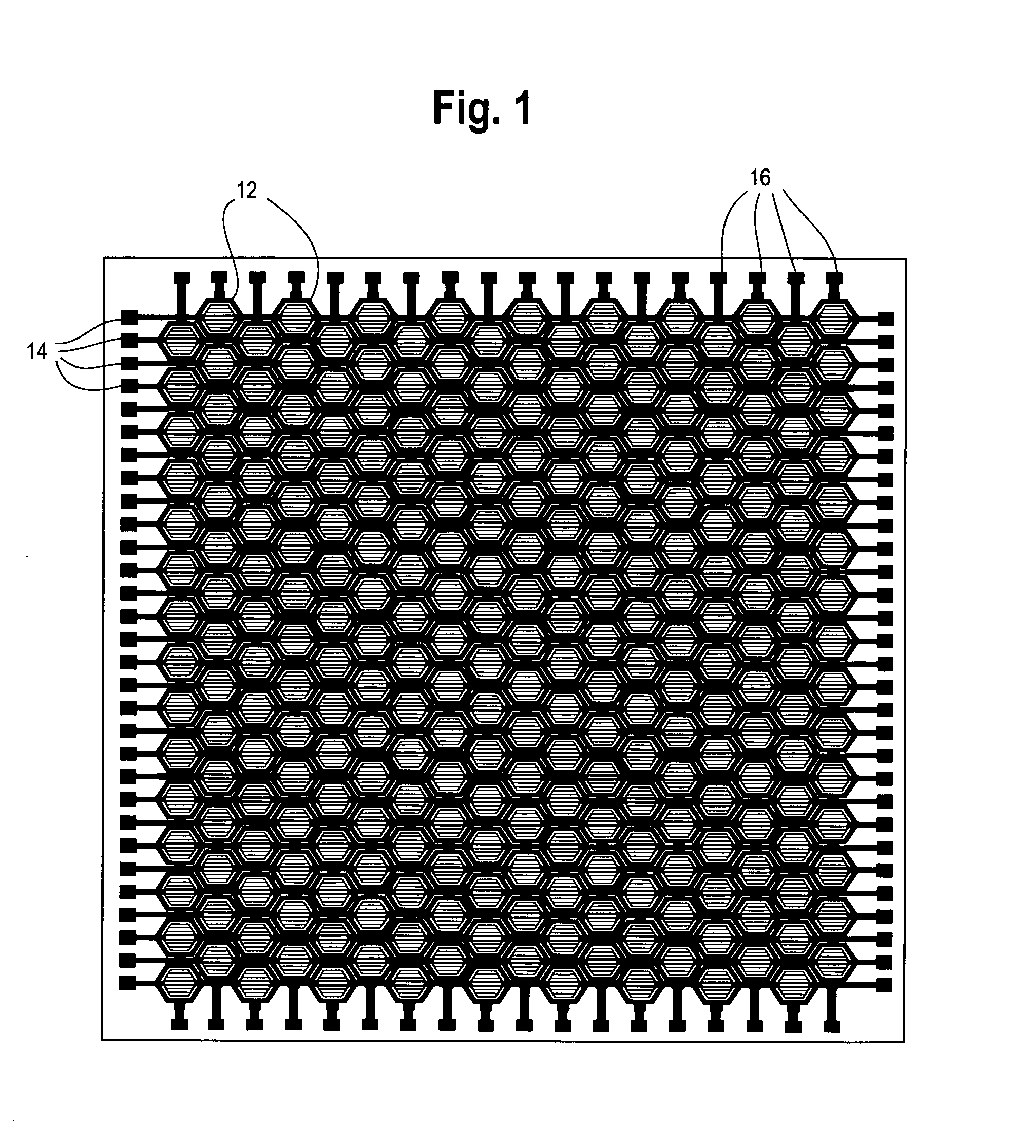
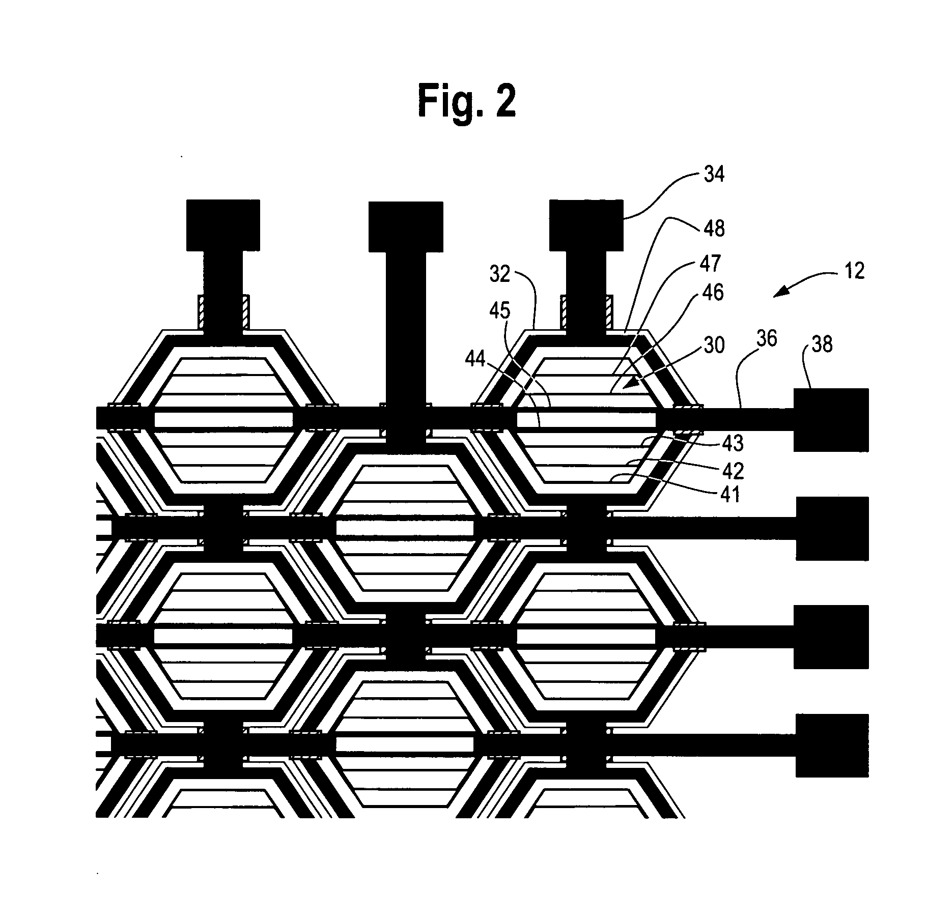
[0011] In accordance with a further feature of the present invention, the LEDs are positioned in the array so that the distance between a center of a first LED and a center of a second, adjacent LED is equal to the distance between a center of the first LED and a center of a third LED where the third LED is adjacent to both the first and second LEDs and the distance between the center of the first LED and the center of the second LED is equal to the distance between the center of the second LED and the center of the third LED so that the centers of the first, second and third adjacent LEDs form vertices of an equilateral triangle. This embodiment of the LED array allows the array to be tightly packed so as to increase the LED density and pixel density of the array, thereby increasing the irradiance of the array.
[0012] In accordance with another feature of the present invention, each LED has a hexagonal shape so as to maximize the packing density of the LEDs and pixels of light generated by the LEDs. The top metallization layer of each of the LEDs is configured to improve current spreading within the active area of the LED while minimizing the amount of light blocked by the metalized lines or traces that provide the current spreading.

Problems solved by technology

However, the laser equipment used for PDT is relatively expensive.
This is a time consuming process for the physician.
Moreover, because the shape of the transparent region is fixed, the light cannot be tailored to match the shape of the diseased tissue.
As such, these filters do not prevent healthy tissue from being irradiated with the therapy light.

Method used


Image

  • PDT apparatus with an addressable LED array for therapy and aiming
  • PDT apparatus with an addressable LED array for therapy and aiming
  • PDT apparatus with an addressable LED array for therapy and aiming

Examples


Embodiment Construction

[0022] An LED array 10, as shown in FIG. 1, provides light to excite a photosensitizer to diagnose or treat diseased tissue of the eye. The array 10 includes a number of LEDs 12 arranged in rows 14 and columns 16 of the array 10. The LEDs 12 of the array 10 are addressable to light each LED individually or to light a group of LEDs together so that the size and shape of the light emitted by the LED array 10 is selectable and can be matched to the size and shape of diseased eye tissue that is targeted to be treated.

[0023] As shown in FIG. 3, the anodes 18 of each LED 12 in a row 14 of the array 10 are connected together. Similarly, the cathodes 20 of each LED 12 in a column 16 of the array 10 are connected together. An individual LED 12 of the array 10 is addressed by coupling drive current to the row of LEDs in which the LED to be lit is located, and by coupling the column, in which the LED to be lit is located, to ground. For example, the LED 12 is addressed so as to light the LED ...


PUM


Abstract

An apparatus for directing light to an eye for exciting a photosensitizer includes an addressable LED array so that the size and shape of the LED light used for aiming or therapy is selectable so as to match the size and shape of targeted tissue. The LED array has a configuration that provides increased LED density, increased current spreading with minimal light blocking and a simplified addressing connection sheme.

Description

CROSS-REFERENCE TO RELATED APPLICATIONS [0001] N / A STATEMENT REGARDING FEDERALLY SPONSORED RESEARCH OR DEVELOPMENT [0002] N / A TECHNICAL FIELD [0003] The present invention relates to an apparatus for directing light to an eye for exciting a photosensitizing agent or photosensitizer to provide therapy for an ocular disease and more particularly to such an apparatus that includes an addressable LED array so that the size and shape of the LED light used for aiming or therapy is selectable so as to match the size and shape of targeted tissue. BACKGROUND OF THE INVENTION [0004] Photodynamic Therapy (PDT) is a known process in which light of a specific wavelength or waveband is directed to tissues undergoing treatment or investigation that have been rendered photosensitive through the administration of a photo-reactive or photosensitizing agent called a photosensitizer. In this therapy, a photosensitizer having a characteristic light absorption waveband is first administered to the patient...

Claims


Application Information

Patent Timeline
IPC IPC(8): A61N5/06
CPCA61F9/0079A61F9/008A61N2005/0659A61N5/062A61N2005/0652A61F2009/00863
Inventor HEACOCK, GREGORYBARNARD, WILLIAMWILLIAMS, WESWATTERS, WAYDE
Owner LIGHT SCI ONCOLOGY
Learn More