Optical Device for Measuring a Doppler Frequency Shift
- Summary
- Abstract
- Description
- Claims
- Application Information
AI Technical Summary
Benefits of technology
Problems solved by technology
Method used
Image
Examples
Example
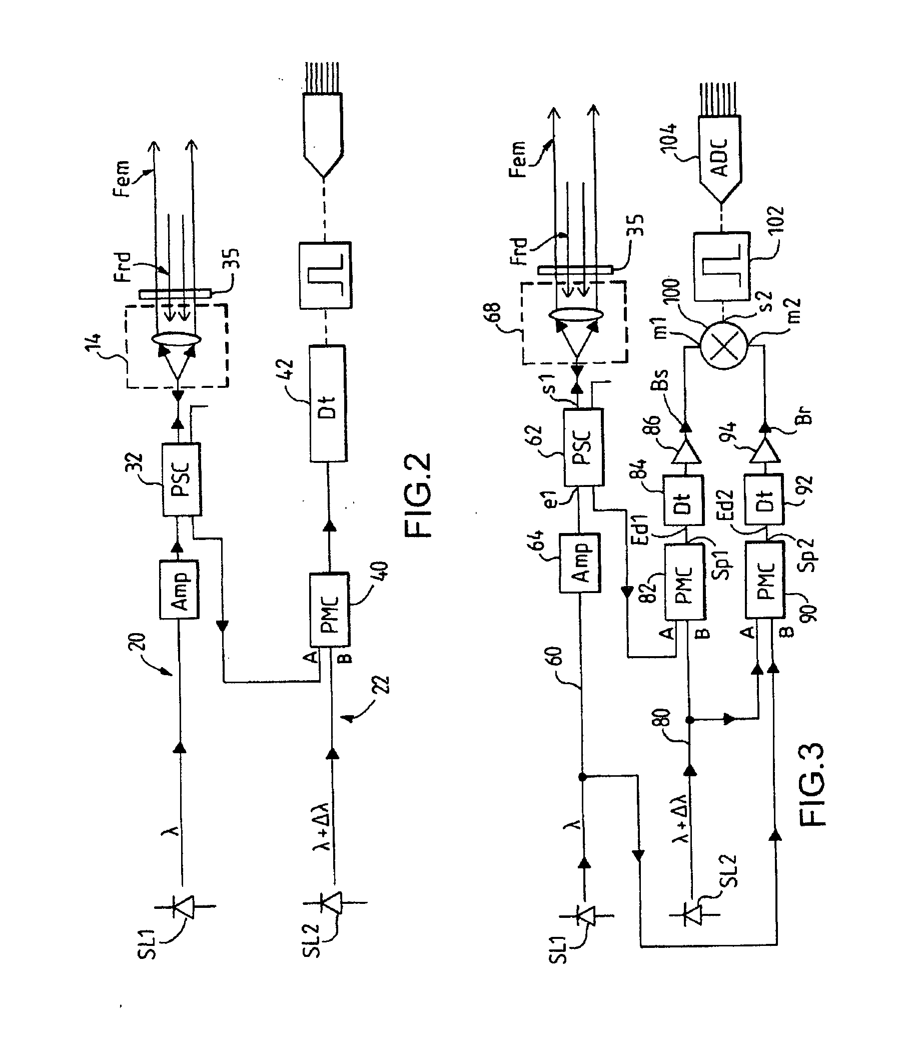
[0043]FIG. 4 shows a first embodiment of the device according to the invention based on the device of FIG. 3. In this first embodiment, the frequency output by the other detector 92 and passing through the amplifier 94 is shifted by a frequency difference HF. For this purpose, the device of FIG. 4 includes another frequency mixer 110 into which are injected, at a mixing input m3, the beat signal Br output by the other detector 92 and passing through the amplifier 94, and, at another mixing input m4, a shift frequency HF, the mixer 110 delivering, via a mixing output s3, a signal that is injected into one of the inputs m2 of the mixer 100, the beat signal Bs output by the detector 84 and passing through the amplifier 86 being injected into the other input m1 of the mixer 100, the mixer 100 delivering, at the outlet s2, a frequency-shifted analog signal HF carrying the Doppler shift which is filtered by the band filter 102 before being digitized by the analog / digital coder ADC 104 for...
Example
[0045]FIG. 5 shows a second embodiment of the device according to the invention based on the device of FIG. 3. In this second embodiment, the device includes a complex frequency mixer MC 112 into which are injected, at a mixing input m5, the beat signal Br output by the other detector 92 and passing through the amplifier 94 and, at another mixing input m6, the beat signal Bs output by the detector 84 and passing through the amplifier 86, the complex mixer MC 112 delivering, via two outputs I and Q, complex signals digitally coded by a respective analog / digital coder ADC 113, 114, digital signals IN and QN output by the respective coders ADC 113, 114 being injected into a baseband signal processing module SPM 115 that delivers the Doppler shift.
Example
[0046]FIG. 6 shows a third embodiment of the device according to the invention based on the device of FIG. 3. In this third embodiment, the laser source SL2 of the reference channel is frequency-adjustable by an electronic frequency control input Cd2. As in the case of the device of FIG. 3, the beat signals Br, Bs output by the respective detectors 84, 92 and passing through the respective amplifiers 86, 94 are injected into the respective inputs m1 and m2 of the mixer 100, which delivers, at its output s2, an analog signal carrying the Doppler shift which is filtered by a band filter 102 before being digitized by an analog / digital coder ADC 104 for extracting the Doppler shift information. In this third embodiment, the device further includes a frequency detector DF 106 into which is injected, at a detection input Edt, the signal at the output s2 of the mixer 100 and which delivers, at an output Sdt of the detector, a control signal Ucl which is injected into the input Cd2 for cont...
PUM
 Abstract
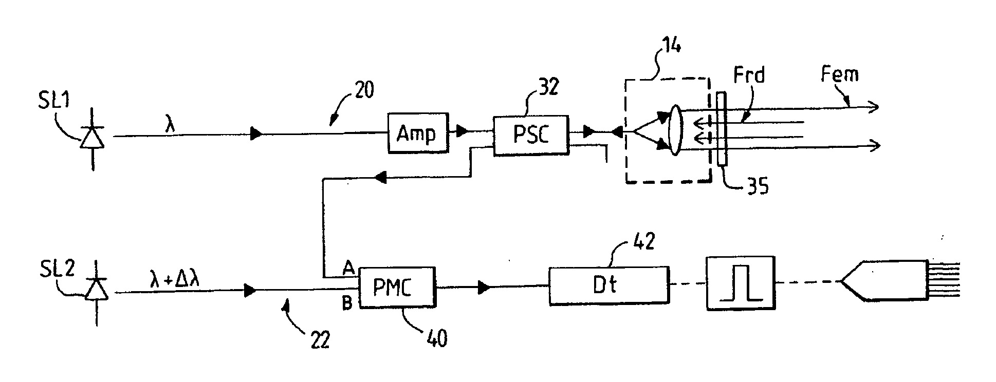
- an optical signal channel (60) delivering a signal light beam illuminating a reference medium;
- a reference channel (80) delivering a reference light beam for detecting the Doppler frequency shift, the frequency shift being determined from the difference in frequency between the light signal illuminating the reference medium and the light beam returned by the reference medium,
- characterized in that it includes at least two light radiation sources (SL1, SL2), preferably lasers, one light radiating source generating the light beam for the signal channel and the other source generating the light beam for the reference channel.
Description
Claims
Application Information
 - R&D
- Intellectual Property
- Life Sciences
- Materials
- Tech Scout
- Unparalleled Data Quality
- Higher Quality Content
- 60% Fewer Hallucinations
Browse by: Latest US Patents, China's latest patents, Technical Efficacy Thesaurus, Application Domain, Technology Topic, Popular Technical Reports.
© 2025 PatSnap. All rights reserved.Legal|Privacy policy|Modern Slavery Act Transparency Statement|Sitemap|About US| Contact US: help@patsnap.com


