
Apparatus to measure absolute velocity and acceleration

Inactive Publication Date: 2007-09-27
BRAUNS ETIENNE
View PDF4 Cites 14 Cited by
  • Summary
  • Abstract
  • Description
  • Claims
  • Application Information

AI Technical Summary

Benefits of technology

[0006]Note: it could be argued that there would be an effect on the linear trajectory in the immediate vicinity of extremely large masses but this effect is of an extremely marginal importance and is to be completely neglected within the geometry and size scale (order of magnitude: 1 meter) of the measurement device of the present invention.
[0007]As a result of this observation, photons (light) can be used in a specific measurement device set-up, which is the subject of the present invention, to measure the absolute velocity of a moving material object. The measurement device is rigidly attached to the material object in order to perform the envisaged object's absolute velocity measurements. Basically, the measuring device includes at least a photon (light) source and a photon sensitive sensor, being mounted rigidly in the apparatus. A laser, generating laser pulses, is preferred as photon source. As an example, the sensor is a perfectly flat electronic CCD device which enables to detect laser pulses at a high spatial pixel resolution. As an example of one possible embodiment, the laser is mounted on the device's rigid frame, according to a perfect geometrical alignment in a way that the emitted laser pulse is geometrically directed perfectly perpendicular towards the CCD sensor's plan

Problems solved by technology

This effect is non refutable, since the laser pulse's linear trajectory is completely independent from the source immediately after being emitted by the laser source.

Method used


Image

  • Apparatus to measure absolute velocity and acceleration
  • Apparatus to measure absolute velocity and acceleration
  • Apparatus to measure absolute velocity and acceleration

Examples


case 2

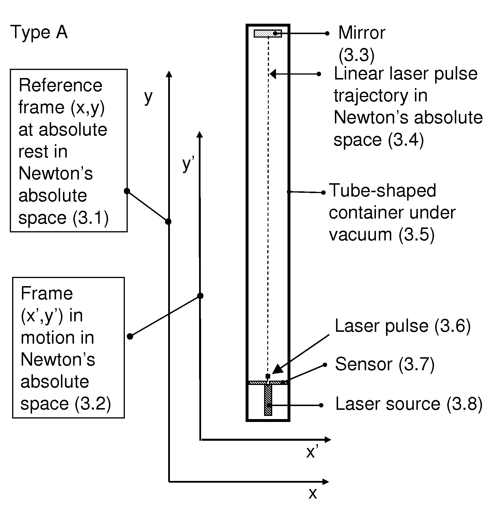
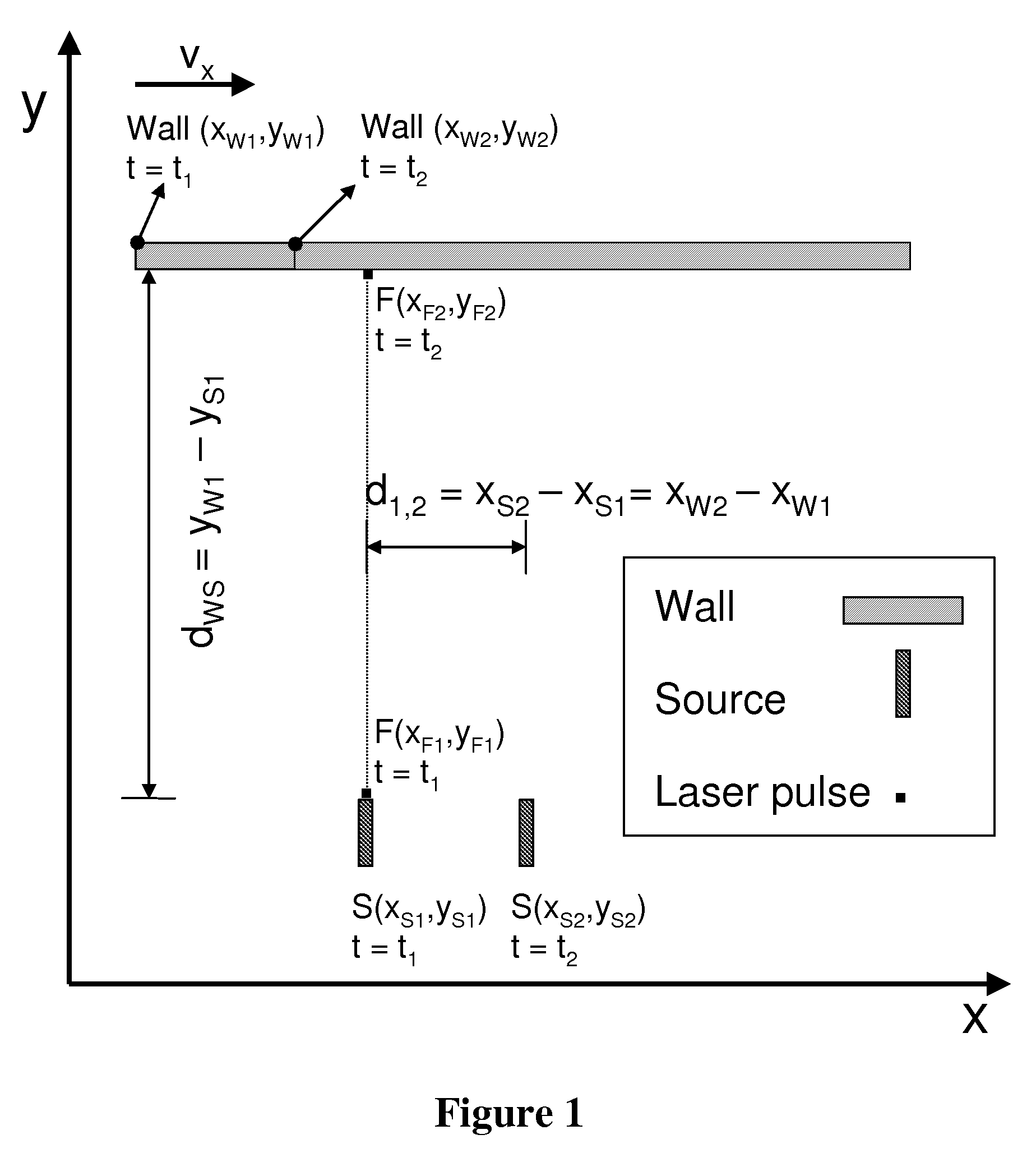
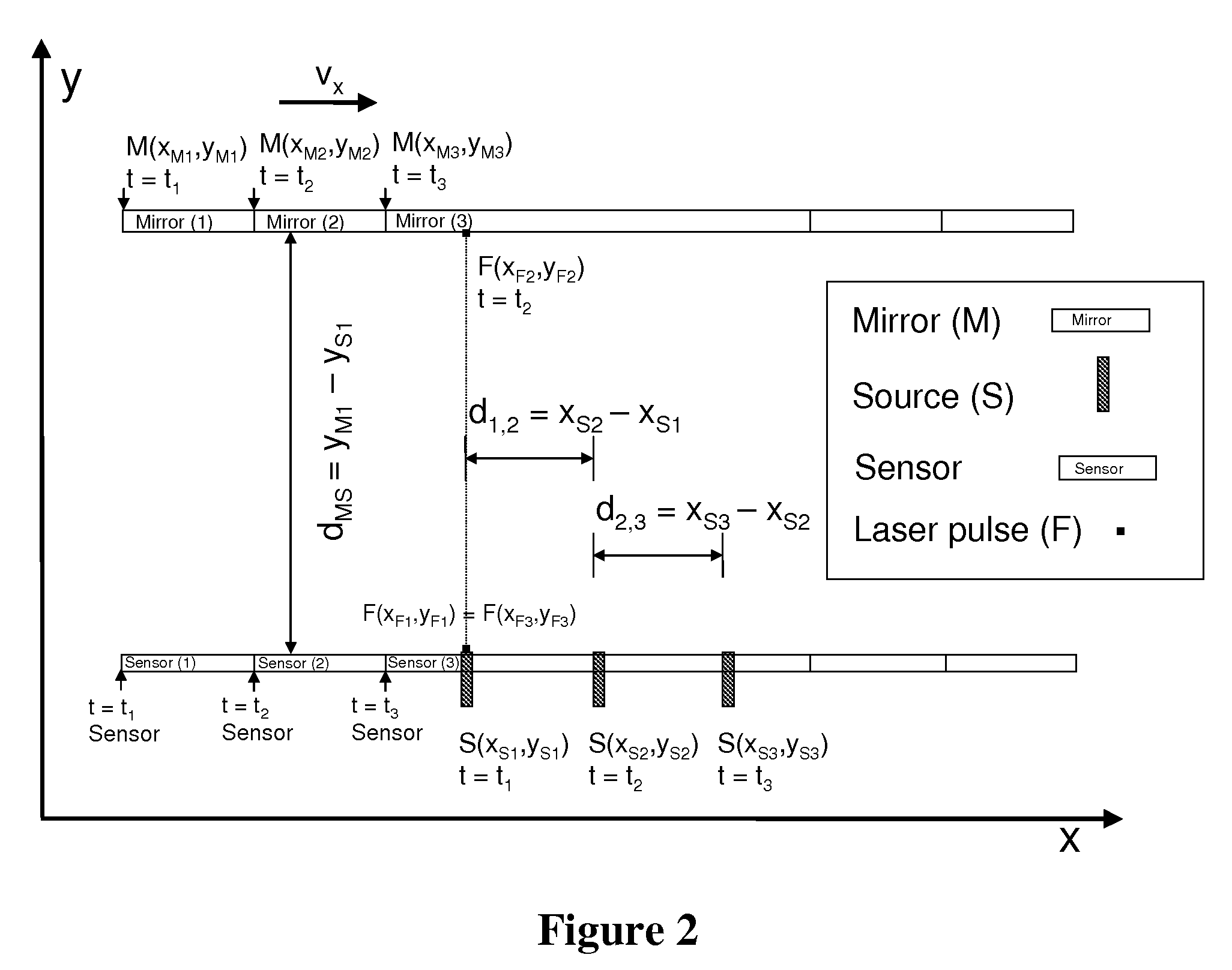
[0037]In FIG. 2, a set-up is illustrated which is only a modification of the set-up as presented in the thought experiment in FIG. 1 and which comprises a mirror in order to reflect the laser pulse while doubling the laser pulse's travelling distance. With such a set-up and having a distance between the laser source and the mirror of 100 m the travelling distance would be in total 200 m (towards the mirror and after reflection back to the sensor) and the corresponding travelling time would be 6,672 10−7 sec. When considering a real experiment on earth with a set-up being based upon FIG. 2 it should be evident to anyone that the set-up is NOT at rest but travels along with our planet through space at a tremendous mean velocity of about 30000 m / sec in the earth's orbit around the sun (while excluding for now the likely separate velocity of our galaxy which should be added then) ! It is thus easy to calculate as a first estimate that:[0038]case 1) when the set-up would be aligned in th...

experiment b

[0179 is performed while:[0180]vx=vx, so now the structure actually is travelling in the x-direction[0181]the observer has programmed the system to fire exactly the laser pulse when XS1=XOBS [0182]the observer evaluates the trajectory of the laser pulse, still from her / his position XOBS

[0183]Since, according to the laws in physics, the source has no effect at all on the laser pulse with respect to velocity, the laser pulse does not inherit the vx component from the laser source and thus travels exactly along the same trajectory as in the first experiment and at the speed of light. So again, the laser pulse travels from the position F(XF1,YF1) along the line y=XOBS towards the position F(XF2,YF2). Again XOBS=XS1=XF1=XF2. The laser pulse needs exactly the same time difference At to travel the distance d from F(XF1,YF1) to F(XF2,YF2). The same value of the speed of light is thus obtained by dividing the distance d by the time Δt.

[0184]Experiment C: the observer decide to perform a thi...

experiment d

[0185] the observer decides to repeat the second experiment B in exactly the same way but the only difference is that the observer's position is switched to the position 1 on top of the rigid structure (FIG. 15). So, now the observer travels along with the experimental structure to see the effect. The observer is clearly aware of the fact that the fourth experiment is programmed in exactly the same way as the second experiment and that nothing was changed with respect to the experimental parameters. Therefore experiment 4 is really a reproduction of experiment 2 and only the position of the observer has changed. Of course the observer's mind is perfectly sure that an observer's position can not influence in any way the outcome of an experiment ! And since in physics a completely reproduced experiment always delivers the same result, the observer is really sure that the fourth experiment must reproduce exactly the same result as obtained within the experimental reality within the sec...


PUM


Abstract

A three-dimensional (x′-axis, y′-axis and z′-axis based) combined light-based apparatus for measuring the absolute velocity and acceleration of a material object in space. The apparatus has for each axis, while each axis is perpendicular to each other axis, an identical set-up of: a photon (light) emitting source; zero to multiple mirrors; a photon sensitive sensor, possibly CCD-based. The emitted photons are directed to the sensor with or without one or multiple reflections from zero to multiple mirrors. The photons, emitted by the source, arrive at the sensor at a location determined by the momentarily absolute velocity of the apparatus in Newton's absolute space; the absolute velocity of the apparatus thus being calculable from this location on the sensor by adequate mathematical formulas. During acceleration, the time derivative of the location's shift is a function of the value of the acceleration of the apparatus; the acceleration of the apparatus is thus calculable from the time derivative of this location's shift by adequate mathematical formulas. If the velocity in only one direction (one dimension) should be measured, a single velocity measuring set-up is adequate.

Description

BACKGROUND OF THE INVENTION [0001]Information about velocity, acceleration and also position of material objects which are moving in space is of prime importance in mechanically oriented technologies or applications, in particular within space travel applications. Up to now, only the measurement of the relative velocity of a moving object was considered to be possible, as a result of relativity considerations, as introduced already by Galileo. Relativity theories exclude the possibility to measure a moving object's absolute velocity. Absolute velocity was defined by Isaac Newton since in Newton's view, absolute velocity must exist since he considered space to be at absolute rest. When thus considering a reference frame at absolute rest in Newton's absolute space, the velocity of a moving material object as measured in such frame is therefore the absolute velocity of the object, according to Newton. However, no experimental evidence could be presented up to now with respect to the ab...

Claims


Application Information

Patent Timeline
IPC IPC(8): G01P3/36
CPCG01P3/50
Inventor BRAUNS, ETIENNE
Owner BRAUNS ETIENNE
Learn More