Injection Nozzle

Inactive Publication Date: 2007-09-27
ROBERT BOSCH GMBH
View PDF6 Cites 7 Cited by
  • Summary
  • Abstract
  • Description
  • Claims
  • Application Information

AI Technical Summary

Benefits of technology

[0004] The injection nozzle according to present invention, with the defining characteristics of claim 1, has the advantage over the prior art that the nozzle needle can be controlled directly by means of a vacuum, which essentially permits less strict manufacturing tolerances to be set. An increased amount of guidance play has the inverse effect of reducing manufacturing costs. Furthermore, in the injection nozzle according to the invention, the increase or reduction of pressure against the control surface can be easily implemented so that no lateral forces are introduced into the nozzle needle or needle unit, which improves the function of the injection nozzle.
[0005] According to an advantageous embodiment form, the coupling piston can at least partially delimit the coupling chamber on a side closer to the at least one injection orifice. The result of this embodiment is that the actuator drives the coupling piston toward the at least one injection orifice, which permits a particularly compact design of the injection nozzle.
[0006] In another advantageous embodiment form, the coupling piston is supported so that it can execute a stroke motion in a cylindrical chamber contained in an insert piece that is situated axially between the actuator and the nozzle needle or needle unit. An insert piece of this kind can easily be manufactured with the required degree of precision, which reduces the manufacturing costs for the injection nozzle.
[0007] In one modification, the cylindrical chamber can contain a return spring, which rests against the coupling piston at one end and rests against a bottom of the cylindrical chamber at the other. To assist the closing of the nozzle needle, a return spring of this kind can prestress the coupling piston into its starting position with a definite return force, which simultaneously results in a definite pressure increase in the coupling chamber and consequently in the control chamber. This makes it possible to increase the effective forces acting on the nozzle needle in the closing direction. The proposed return spring thus assists the closing motion of the nozzle needle.

Problems solved by technology

Strict manufacturing tolerances, however, are accompanied by comparatively high manufacturing costs.
This can lead to an increased friction between the nozzle needle and its needle guide, which can impair proper function of the nozzle needle.

Method used


Image

  • Injection Nozzle
  • Injection Nozzle
  • Injection Nozzle

Examples


Embodiment Construction

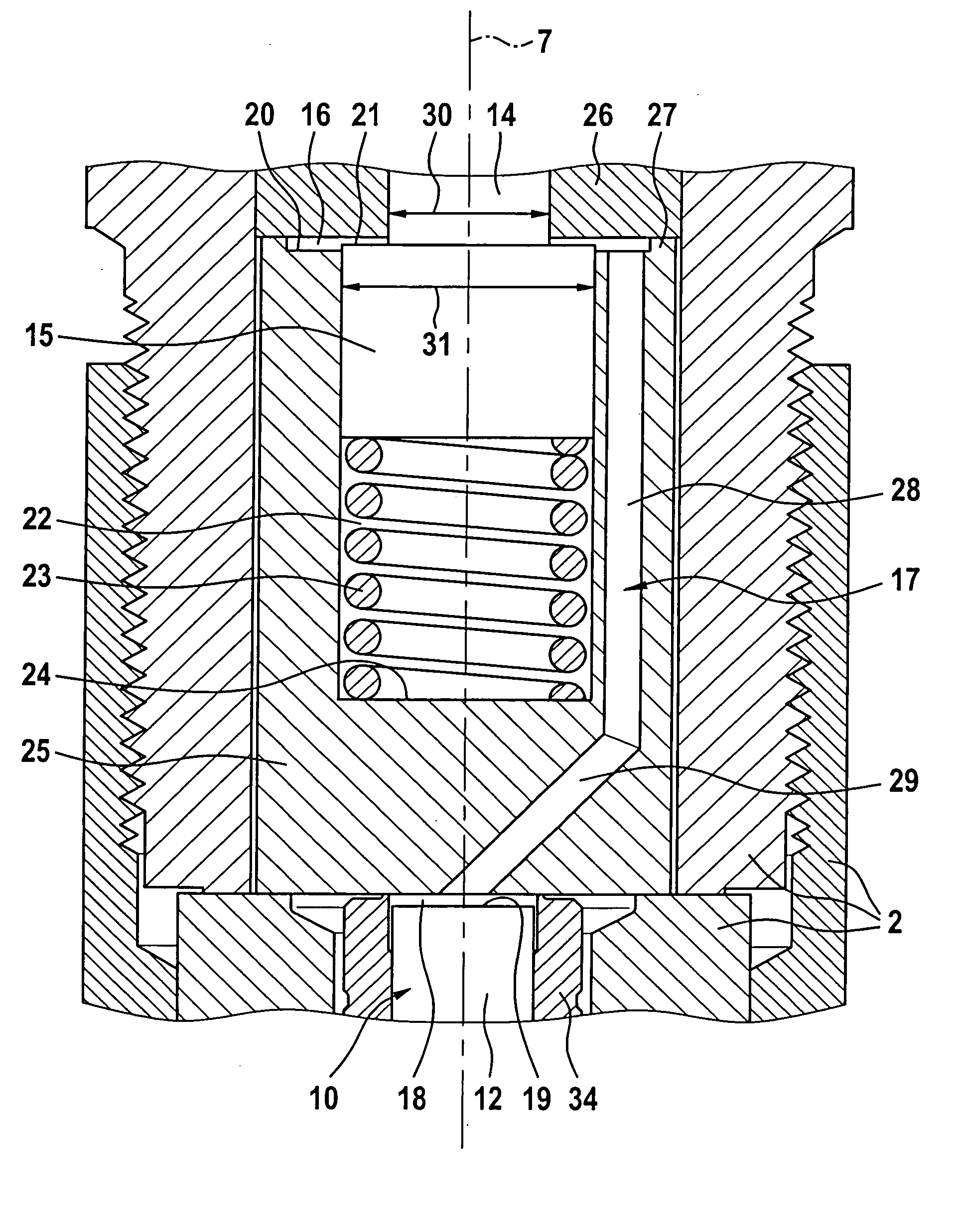
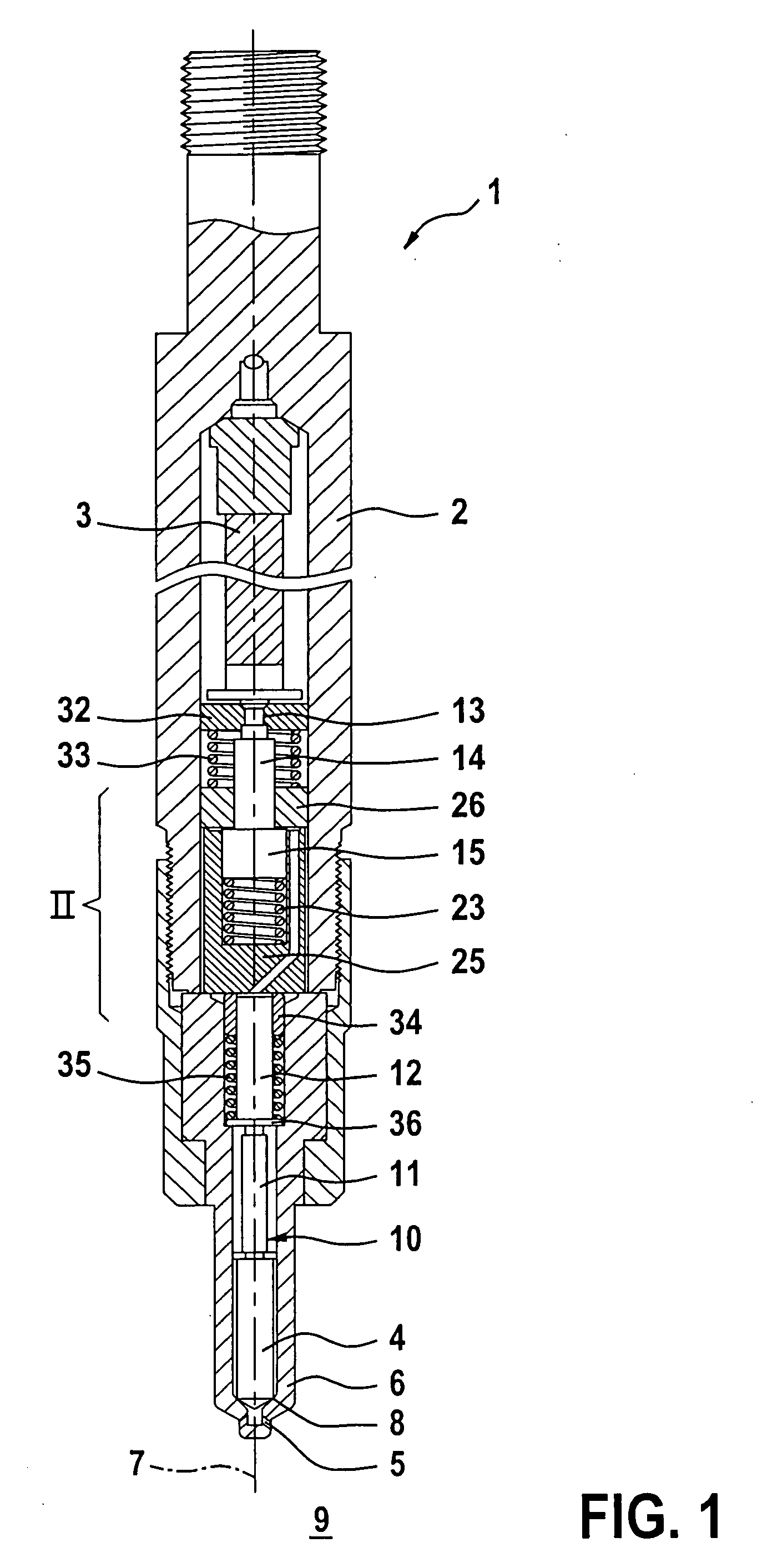
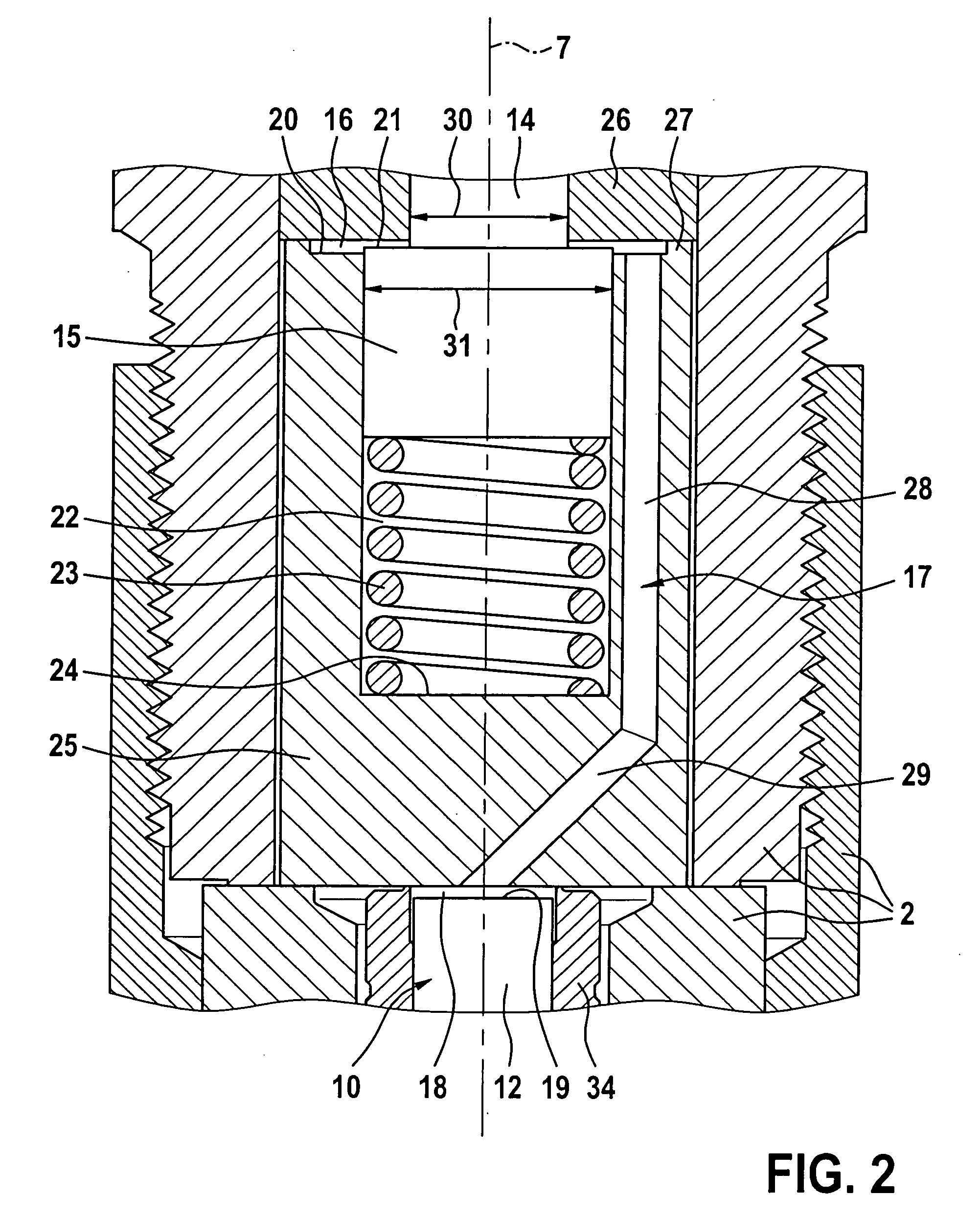
[0012] According to FIG. 1, an injection nozzle 1 according to the invention includes a nozzle body 2 that contains an actuator 3 and a nozzle needle 4. The actuator 3 is preferably embodied as a piezoelectric actuator 3, i.e. a piezoactuator 3, whose axial length increases when acted on with current and decreases again when the current is switched off. The nozzle needle 4 is used to control an injection of fuel through at least one injection orifice 5 situated in a nozzle tip 6. Usually, the injection nozzle 1 has a number of injection orifices 5, which can be arranged in an approximate star shape in relation to a longitudinal central axis 7 of the nozzle needle 4 and the injection nozzle 1. The nozzle needle 4 cooperates with a needle seat 8. When the nozzle needle 4 is in the closed state, it rests against its needle seat 8 and disconnects the at least one injection orifice 5 from a fuel supply, not shown in detail, in which the fuel to be injected is kept in readiness at a relat...


PUM


Abstract

The invention relates to an injection nozzle for an internal combustion engine having a nozzle needle or needle unit for controlling an injection of fuel through at least one injection orifice and an actuator for driving a coupling piston. The nozzle needle or needle unit has a control surface that at least partially delimits a control chamber which communicates with a coupling chamber that is at least partially delimited by the coupling piston. The control surface is situated at the end of the nozzle needle or nozzle unit oriented away from the at least one injection orifice and the actuator drives the coupling piston to open the nozzle needle in such a way that a volume of the coupling chamber increases.

Description

PRIOR ART [0001] The invention relates to an injection nozzle for an internal combustion engine, in particular in a motor vehicle, with the defining characteristics of the preamble to claim 1. [0002] U.S. Pat. No. 6,520,423 B1 has disclosed an injection nozzle of this kind that has a nozzle needle for controlling an injection of fuel through at least one injection orifice. The injection nozzle also has a piezoelectric actuator for driving a coupling piston that protrudes into a coupling chamber and at least partially delimits it. The nozzle needle or a needle unit that contains the nozzle needle has a control surface that at least partially delimits a control chamber and communicates with the coupling chamber. In the known injection nozzle, the control surface is situated at an end of the nozzle needle or needle unit oriented toward the at least one injection orifice. In order to open the nozzle needle, the actuator in the known injection nozzle drives the coupling piston so that it...

Claims


Application Information

Patent Timeline
IPC IPC(8): F02M61/18F02M47/02F02M51/06F02M61/16F02M61/20F02M63/00
CPCF02M51/0603F02M2200/704F02M61/205F02M61/168
Inventor STOECKLEIN, WOLFGANGRAPP, HOLGERSCHWARZ, THOMASGRUENBERGER, ANDREAS
Owner ROBERT BOSCH GMBH
Why Eureka
Try Eureka