
Method and apparatus for engine torque sensing

a technology of engine torque and torque measurement, applied in the direction of apparatus for force/torque/work measurement, instruments, tension measurement, etc., can solve the problems of limiting the accuracy and reliability of these estimation modules, affecting the control strategies of high-performance engines and transmissions currently prevalent in automotive vehicles, and conventional engine torque estimation methods insufficient to achieve the stated goals of new powertrain control strategies. , the effect of reducing packaging concerns

Active Publication Date: 2007-09-27
GM GLOBAL TECH OPERATIONS LLC
View PDF4 Cites 25 Cited by
  • Summary
  • Abstract
  • Description
  • Claims
  • Application Information

AI Technical Summary

Benefits of technology

[0006] Responsive to these and other concerns presented by conventional engine torque estimation systems and crankshaft torque sensors, the present invention concerns an improved engine torque sensing technique that directly measures deformations on the surface of a disk, such as a flexplate or a flywheel transmitting engine torque to a vehicle gearbox (transmission system or torque converter). In direct contrast to conventional crankshaft-mounted sensors, measuring the torque through the flexplate significantly alleviates packaging concerns by utilizing the larger surface area provided by the disk. Among other things, this invention is useful for providing a faster and more accurate method of determining actual engine torque values, which in turn can be used to improve powertrain calibration, engine performance, transmission control, engine-transmission matching, chassis / vehicle control, and driveability. The relatively lower costs, ease of packaging, and minimal required modifications to the production configuration associated with the direct torque sensors of the present invention are expected to facilitate faster integration in automotive vehicles. Finally, the present invention is further useful for providing real-time feedback, and therefore, more efficient and accurate engine torque control under a closed-loop system.

Problems solved by technology

The limited accuracy and reliability of these estimation modules, however, present fidelity concerns that impede high performance engine and transmission control strategies currently prevalent in automotive vehicles.
As subsystems, including those related to emissions, fuel economy and driveability, become increasingly more complex, their proper performance require more accurate torque determination, making conventional engine torque estimation methods insufficient to achieve the stated goals of new powertrain control strategies.
Conventional direct engine torque sensors, however, present various packaging, cost, performance, and reliability concerns.
First, these sensors are relatively complex and expensive to produce in comparison to other vehicle components, and therefore, have yet to become fully implemented in the mass production of automotive vehicles.
Another obstacle to mass production is the lack of required space on or near the crankshaft for sensor integration in production vehicles.
No earlier attempts at installing the sensor on the crankshaft have led to a method viable for mass production, as they require significant engine modifications.
Finally, the limited bandwidth typically presented in these sensors provide insufficient capabilities for optimization tasks, such as shift point optimization or spark timing control on an individual-cylinder individual-event basis for the full range of engine operating conditions.

Method used


Image

  • Method and apparatus for engine torque sensing
  • Method and apparatus for engine torque sensing
  • Method and apparatus for engine torque sensing

Examples


Embodiment Construction

)

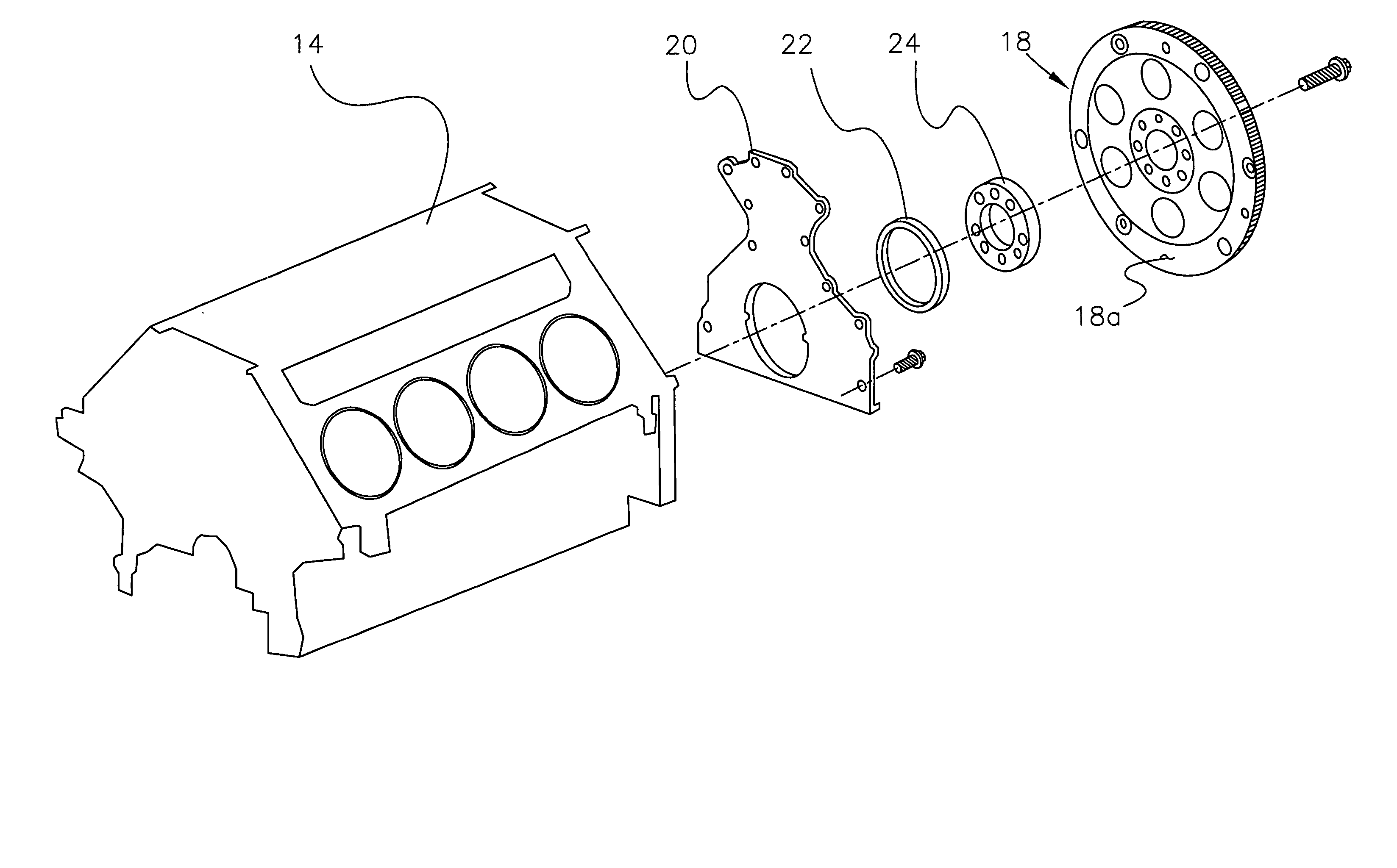
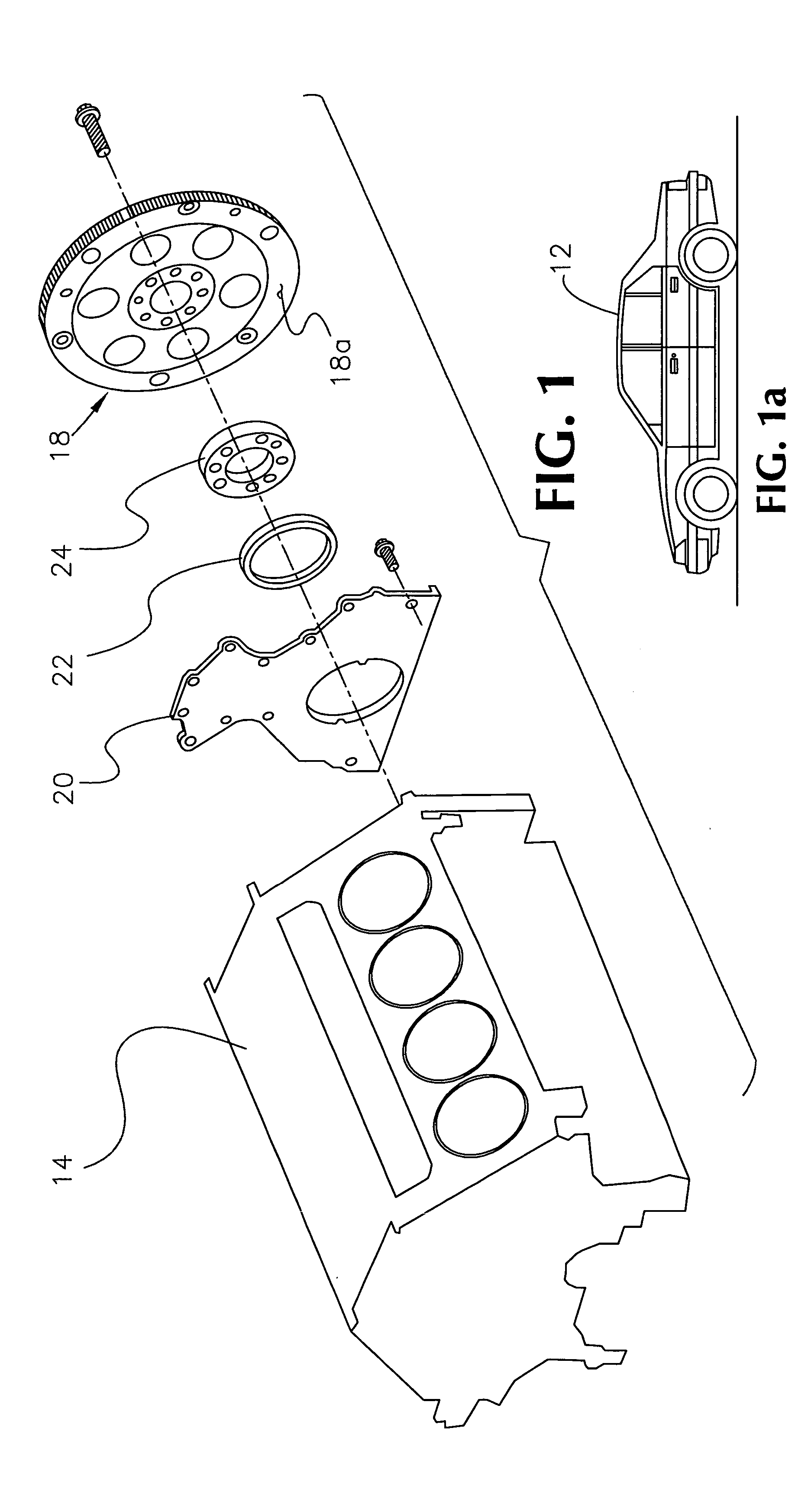
[0030] The present invention concerns an improved direct engine torque sensory system 10 adapted for use by a vehicle 12 having an engine 14, a crankshaft 16 connected to the engine 14, and a flexplate 18 fixedly attached to the crankshaft 16. As is typical, the crankshaft 16 and engine 14 are cooperatively configured to convert the linear displacement of engine components (not shown) into the rotational displacement of the crankshaft 16 and flexplate 18. In FIG. 1, an exemplary conventional engine / flexplate assembly is shown, wherein the flexplate 18 is connected by a flexplate bolt to the rear of the engine block 14, and preceded sequentially by a crankshaft rear oil seal housing 20, a crankshaft rear oil seal 22, and a flexplate spacer 24.

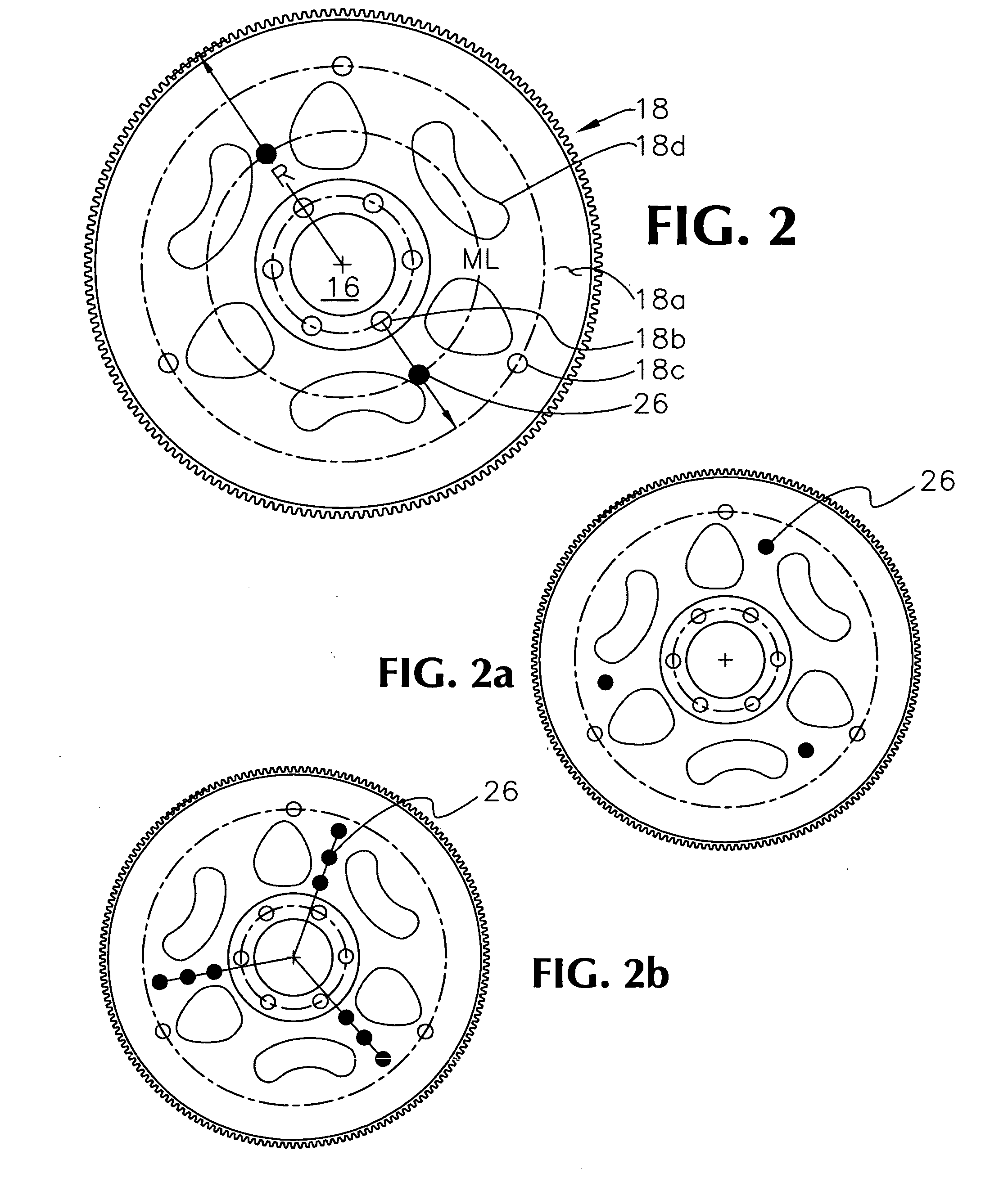
[0031] The preferred flexplate 18 presents a disk with gearteeth on the rim, as is illustrated and conventionally used in the art (see, FIGS. 2 through 3b). For example, a suitable flexplate 18 having 168 teeth, and a 35.6 cm (14-inches) outsi...


PUM


Abstract

An engine torque sensory system (10), adapted for use with an engine-driven vehicle (12) having a flexplate (18), including at least one sensor (26) fixedly attached on the surface of the flexplate (18) and operable to detect deformations along the surface of the flexplate (18) caused by the generated engine torque, and further including a receiver (28) communicatively coupled to the sensor (26), spaced from the rotating flexplate (18), and operable to convert sensor readings to correlative engine torque values.

Description

TECHNICAL FIELD [0001] The present invention relates to engine torque sensors, and more particularly, to a direct engine torque measurement system using flexplate deformations under torsional load application, wherein said system includes a flexplate-mounted sensor. BACKGROUND OF THE INVENTION [0002] Engine torque sensors have been developed to help regulate and optimize various aspects of motor-driven vehicular performance. For example, to improve automotive vehicle driveability in powertrain applications, it is desirable to coordinate engine and transmission control functions. Transmission control algorithms in powertrains use torque information from the engine controller under a wide variety of powertrain operating conditions to improve shift quality, fuel economy, and drivability. Engine torque sensing is used to improve other aspects of performance, such as cold-start driveability, combustion optimization, and cylinder-balancing. [0003] For internal combustion engines, in-cylin...

Claims


Application Information

Patent Timeline
Patent Type & Authority Applications(United States)
IPC IPC(8): G01M15/00
CPCG01L3/1428
Inventor JAVAHERIAN, HOSSEIN
Owner GM GLOBAL TECH OPERATIONS LLC
Learn More