
Soft-start circuit and method for low-dropout voltage regulators

a voltage regulator and soft-start technology, applied in the field of low-dropout voltage regulators, can solve the problems of circuits susceptible to large inrush currents, unusable resets, overload of busses, etc., and achieve the effects of low cost, easy customization of control, and minimal die area

Active Publication Date: 2007-09-20
TEXAS INSTR INC
View PDF6 Cites 51 Cited by
  • Summary
  • Abstract
  • Description
  • Claims
  • Application Information

AI Technical Summary

Benefits of technology

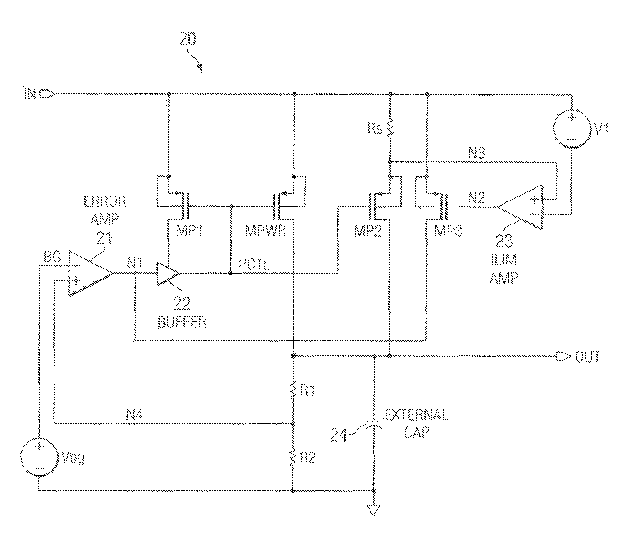
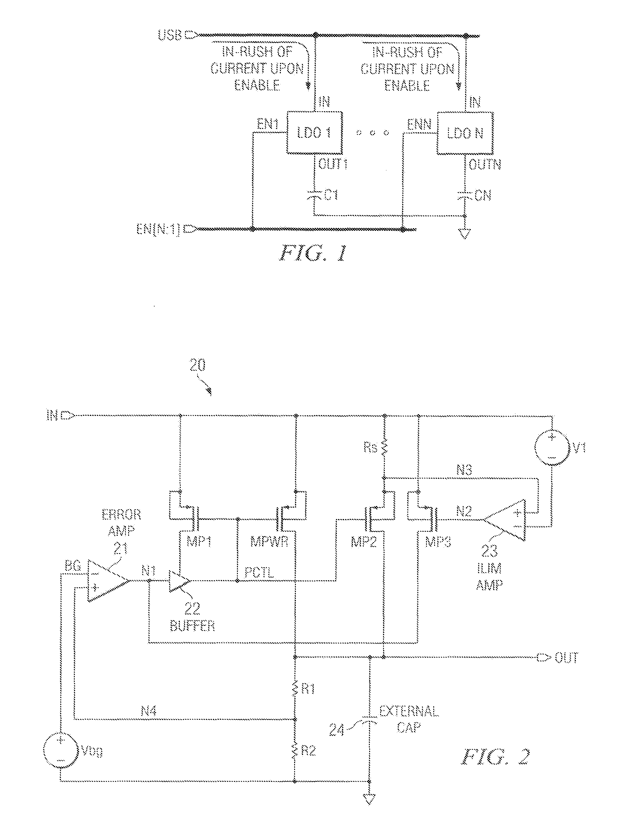
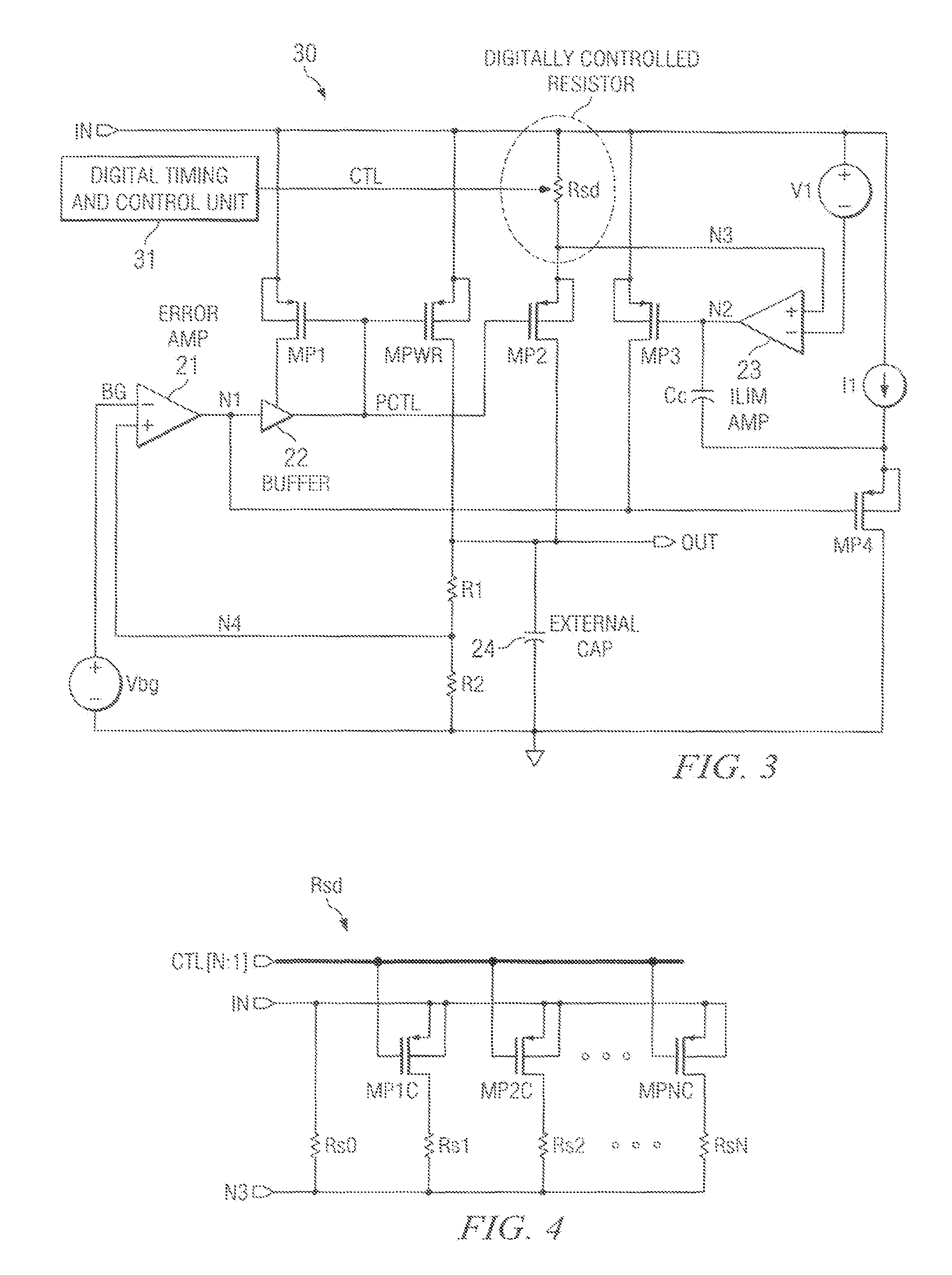
[0009]Prior art voltage-based techniques for soft-start only allow open loop control of the input voltage (i.e. no closed-loop monitoring of the current through the power FET). But, the invention provides a closed-loop current-limit-based positively-controlled increase in the output voltage during start-up. In some embodiments of the invention, the profile of the soft-start may be programmably controlled in the digital domain, providing easily customizable control of soft-start by the designer. The invention may be implemented with minimal die area and thus is a very cost-effective solution.

Problems solved by technology

Such an inrush of current can easily cause the system to malfunction, or cause an undesirable reset.
This is so even if the full load current of the LDO regulator during steady-state operation is less than the maximum current the USB bus can handle, because during start-up, large current transients can occur, thus causing overload of the bus.
Each of the N bus lines has its own separate LDO regulator circuit, and each such regulator circuit is susceptible to large inrush currents upon enable.
This method, while successful in many cases, can still fail for certain start-up conditions in which a sudden switching of load current through the LDO voltage regulator may still be activated.

Method used


Image

  • Soft-start circuit and method for low-dropout voltage regulators
  • Soft-start circuit and method for low-dropout voltage regulators
  • Soft-start circuit and method for low-dropout voltage regulators

Examples


Embodiment Construction

[0015]The making and use of the various embodiments are discussed below in detail. However, it should be appreciated that the present invention provides many applicable inventive concepts which can be embodied in a wide variety of specific contexts. The specific embodiments discussed are merely illustrative of specific ways to make and use the invention, and do not limit the scope of the invention.

[0016]As mentioned above, prior art LDO voltage regulators with soft-start circuitry can still cause problems for certain start-up conditions in which a sudden switching of load current from the LDO voltage regulator through its power FET is activated. The invention provides a solution by providing a soft-start that ensures that the transient current during start-up never exceeds a certain value. Some embodiments of the invention have the further improvement of providing the versatility of programming different start-up profiles as demanded by the application or customers. This enables a d...


PUM


Abstract

A low drop-out voltage regulator having soft-start. A low drop-out regulator circuit is provided having an input node, an output node, a power FET connected by a source and drain between the input node and the output node, and a feedback circuit having an output connected and providing a control signal to a gate of the power FET. A current limit circuit is configured to control the power FET to limit the current through it when the voltage across a controllable sense resistor connected to conduct a current representing the current through the power FET exceeds a predetermined limit value. At start-up, control unit provides a control signal to the controllable resistor to cause the resistance value of the controllable resistor to decrease incrementally in value at respective predetermined incremental times during a predetermined time interval.

Description

CROSS-REFERENCE TO RELATED APPLICATIONS[0001]This application claims the benefit of priority of the U.S. Patent Application Ser. No. 60 / 782,643, filed Mar. 15, 2006.TECHNICAL FIELD OF THE INVENTION[0002]The present invention relates to low dropout voltage regulators having current limiting.BACKGROUND OF THE INVENTION[0003]A widely used type of linear voltage regulators is the low dropout (“LDO”) voltage regulator. Dropout voltage is the term used to describe the minimum voltage across a regulator that is required to maintain output voltage regulation. LDO voltage regulators are widely used in modern low voltage (battery) power management integrated circuits (“ICs”) since they maximize the utilization of the available input voltage and can operate with higher efficiency than other types of voltage regulators.[0004]Typical applications usually require that the LDO voltage regulator start as quickly as possible upon enable. Recently, however, many IC customers are demanding LDO voltage...

Claims


Application Information

Patent Timeline
IPC IPC(8): G05F1/00
CPCG05F1/468Y10S323/901Y10S323/908
Inventor AL-SHYOUKH, MOHAMMAD A.MARTINS, MARCUS M.AKSIN, DEVRIM YILMAZ
Owner TEXAS INSTR INC
Learn More