
Coatings for implantable medical devices

Inactive Publication Date: 2007-09-13
SAHAJANAND MEDICAL TECH PVT
View PDF49 Cites 71 Cited by
  • Summary
  • Abstract
  • Description
  • Claims
  • Application Information

AI Technical Summary

Benefits of technology

[0069]expanding the balloon at one or more sel

Problems solved by technology

Various insults to these passageways (e.g., injury, surgical procedures, inflammation or neoplasms) can produce narrowing or even obstruction of such body passageways, with serious consequences that may ultimately result in death.
Frequently, however, the body responds to the implanted stent by ingrowth into the lumen of the stent, thereby again narrowing or blocking the passageway into which the stent was placed.
Upon pressure expansion of an intracoronary balloon catheter during angioplasty, both endothelial and smooth muscle cells within the vessel wall become injured, initiating proliferative, thrombotic and inflammatory responses that ultimately can lead to occlusion of the implanted stent.
However, bleeding and other complications may occur from the use of aggressive treatments such as anticoagulants (e.g., clopidogrel, LMW, heparin, ticlopidine, aspirin or any other GP IIb / IIIa inhibitors).

Method used


Image

  • Coatings for implantable medical devices
  • Coatings for implantable medical devices
  • Coatings for implantable medical devices

Examples


example 1

Manufacture of Drug Eluting Stent

[0181]The stents were manufactured from surgical grade Stainless Steel 316 L tube. Tubes were first cut with a laser machine according to a programmed design. The cut stents were electropolished for surface smoothness. The polished stents were then transferred to a clean room for a quality check. In a coating room, the stents were coated with paclitaxel. The coated stents were crimped on rapid exchange balloon catheters. The packed stents were sterilized with EtOH. A quality check was carried out at each and every stage and non-conforming stents were rejected.

example 2

Preparation of Heparinized Poly-L-Lactide (PLLA)

[0182]The synthesis of a heparinized poly-l-lactide is outlined below.

Materials

[0183]1) poly-l-lactide (inherent viscosity=2.6−3.2 dL / g)

[0184]2) heparin sodium (from porcine intestinal mucosa, 150-190 lU / mg)

[0185]3) dicyclohexylcarbodiimide (DCC)

[0186]4) 4-(dimethyl amino) pyridine (DMAP)

[0187]5) formamide

[0188]6) N,N-dimethyl formamide (DMF)

Method

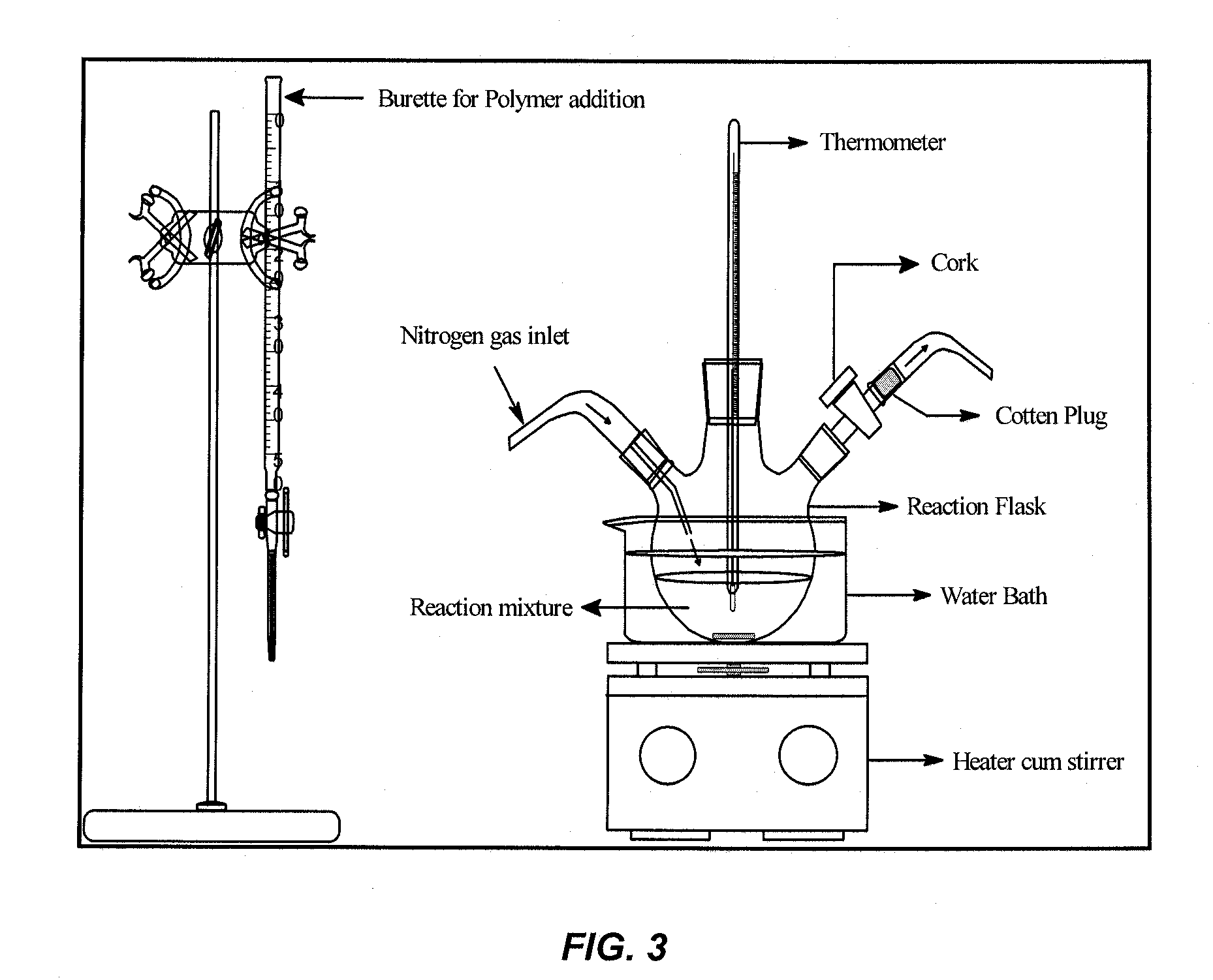
[0189]Heparin-conjugated PLLA was prepared by a direct coupling reaction using dicyclohexylcarbodiimide (DCC) / 4-(dimethyl amino) pyridine (DMAP). The experimental set-up is depicted in FIG. 2.

[0190]Heparin (0.6 g, 1×10⁻⁴ mol) and PLA (6.0 g, 0.5×10⁻⁴ mol) were first dissolved in the N,N-dimethyl formamide (250 ml) and dichloromethane (DCM, 500 ml), respectively. The heparin solution was stirred and heated in a round bottom flask for 1 hr at a temperature of 50-55° C. Solutions of DCC (0.02 ml 0.1 M) and DMAP (0.2 ml 1.0 M) were then added to the heparin solution followed by addition of the PL...

example 3

Preparation of Heparinized 50 / 50 Poly-D,L-Lactide-co-Glycolide

[0192]The synthesis of a heparinized 50 / 50 poly-d,l-lactide-co-glycolide is outlined below.

Materials

[0193]1) 50 / 50 Poly L-Lactide-co-Glycolide (PLGA)

[0194]2) heparin sodium (from porcine intestinal mucosa, 150-190 lU / mg)

[0195]3) dicyclohexylcarbodiimide (DCC)

[0196]4) 4-(dimethyl amino) pyridine (DMAP)

[0197]5) N,N-dimethyl formamide (DMF)

Method

[0198]Heparin-conjugated PLGA was prepared by a direct coupling reaction using dicyclohexylcarbodiimide (DCC) / 4-(dimethyl amino) pyridine (DMAP) chemistry with an experimental set-up as described in Example 2.

[0199]Heparin (0.6 g, 1×10⁻⁴ mol) and PLGA (6.0 g, 0.5×10⁻⁴ mol) were first dissolved in the N,N-dimethyl formamide (250 ml) and dichloromethane (DCM, 500 ml), respectively. The heparin solution was stirred and heated in a round bottom flask for 1 hr at a temperature of 50-55° C. Solutions of DCC (0.05 ml 0.1 M) and DMAP (0.5 ml 1.0 M) were then added to the heparin solution fol...


PUM

PropertyMeasurementUnit
Compositionaaaaaaaaaa
Concentrationaaaaaaaaaa
Surface areaaaaaaaaaaa

Abstract

A composition comprising at least one polymer covalently bonded to heparin, and at least one pharmaceutically active agent other than heparin dispersed within the at least one polymer.

Description

RELATED APPLICATIONS[0001]This application claims the benefit of priority to U.S. Provisional Patent Application Ser. No. 60 / 862,270 filed Oct. 20, 2006, entitled “Coatings For Implantable Medical Devices”; U.S. Provisional Patent Application Ser. No. 60 / 862,265 filed Oct. 20, 2006, entitled “Compositions Comprising Porous Articles And Uses In Implantable Medical Devices”; U.S. Provisional Patent Application Ser. No. 60 / 862,263 filed Oct. 20, 2006, entitled “Compositions and Coatings For Implantable Medical Devices”; U.S. Provisional Patent Application Ser. No. 60 / 832,383 filed Jul. 21, 2006, entitled “Drug Coated and Releasing Balloon Catheters”; U.S. Provisional Patent Application Ser. No. 60 / 814,973 filed Jun. 20, 2006, entitled “Drug Eluting Stent”; and U.S. Provisional Patent Application Ser. No. 60 / 780,121 filed Mar. 8, 2006, entitled “Drug Eluting Stent”, the disclosures of all of the foregoing of which are incorporated herein by reference.FIELD OF THE INVENTION[0002]The pres...

Claims


Application Information

Patent Timeline
IPC IPC(8): A61F13/00
CPCA61K31/337A61K31/352A61L2300/61A61L2300/608A61L2300/604A61L2300/42A61L2300/416A61L33/08A61L31/16A61L31/148A61L31/146A61L31/129A61L31/10A61K31/353A61K31/436A61K31/496A61K31/7048A61K31/727A61K47/48992A61L29/085A61L29/126A61L29/146A61L29/148C08L39/06C08L5/10C08L67/04A61K47/6957
Inventor PATRAVALE, VANDANA B.KOTHWALA, DEVESH M.RAVAL, ANKUR J.KOTADIA, HARESH D.KOTADIA, DHIRAJLALMANAGOLI, NANDKISHORE
Owner SAHAJANAND MEDICAL TECH PVT
Learn More