Magnetic recording medium, magnetic recording apparatus, and servo demodulation circuit

a technology of servo demodulation and magnetic recording medium, which is applied in the direction of maintaining head carrier alignment, recording signal processing, instruments, etc., can solve the problems of increasing the requirements for the performance level of magnetic disc apparatus in terms of data transfer rate and storage capacity, becoming more difficult to manufacture reproducing head, and difficult to achiev

Inactive Publication Date: 2007-09-13
TOSHIBA STORAGE DEVICE CORP
View PDF12 Cites 27 Cited by
  • Summary
  • Abstract
  • Description
  • Claims
  • Application Information

AI Technical Summary

Benefits of technology

[0012] It is an object of the present invention to at least partially solve the problems in the conventional technology.

Problems solved by technology

In recent years, as the performance level of calculators has improved, the requirements for the performance level of magnetic disc apparatuses in terms of data transfer rates and storage capacities have become more demanding.
When the track pitch is small, however, data is written to an adjacent track due to a magnetic field leakage from a lateral face of the magnetic head, and a crosstalk occurs when the data is reproduced.
One problem is that it becomes more difficult to manufacture the reproducing head as the size of the reproducing head becomes smaller.
Another problem is that it is difficult to do so.
For this reason, it is getting to be an important issue how precisely the track position of a magnetic head used for recording and reproducing data can be determined and also how the fluctuations and imbalance in the position of the magnetic head can be diminished.

Method used


Image

  • Magnetic recording medium, magnetic recording apparatus, and servo demodulation circuit
  • Magnetic recording medium, magnetic recording apparatus, and servo demodulation circuit
  • Magnetic recording medium, magnetic recording apparatus, and servo demodulation circuit

Examples


first embodiment

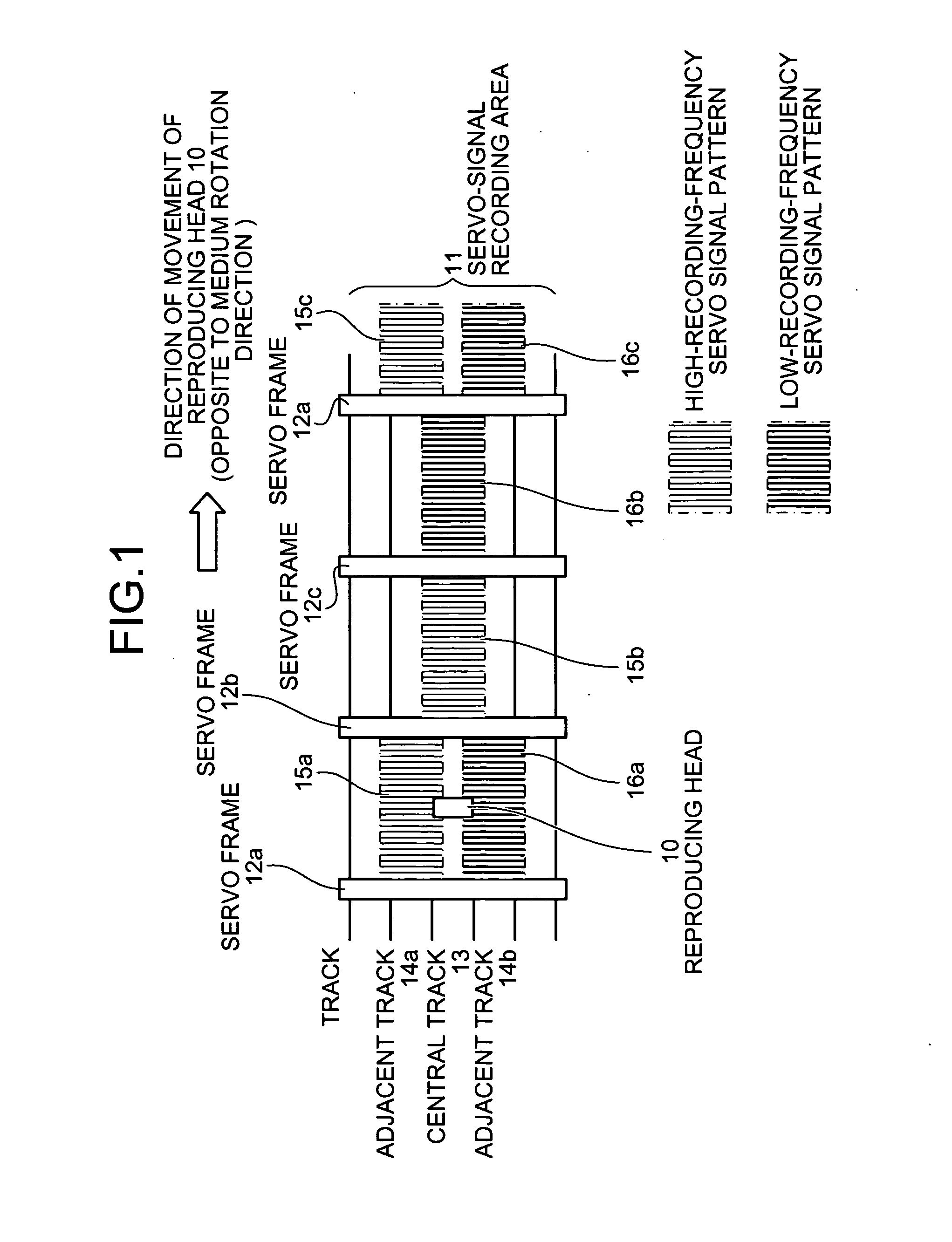
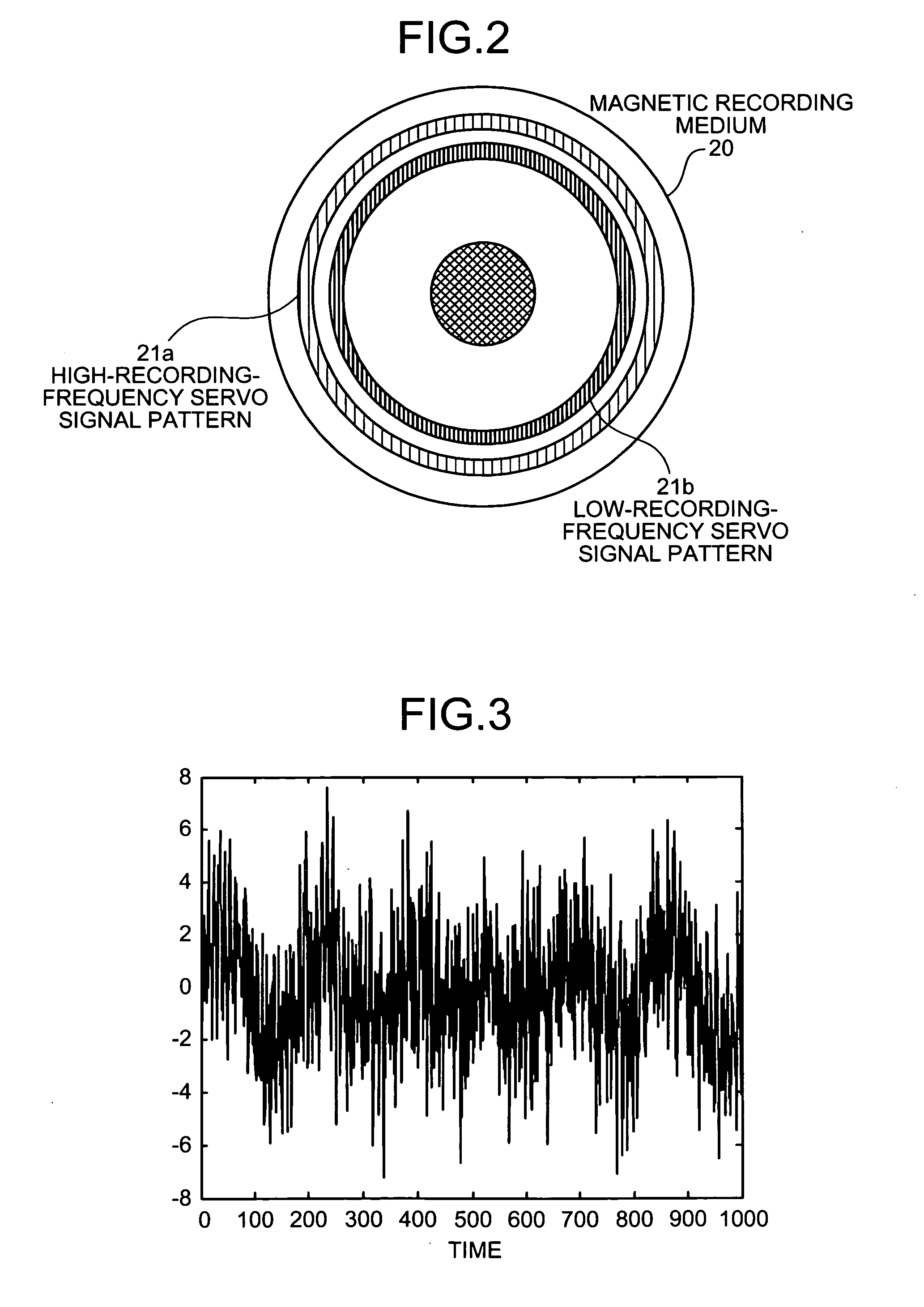
[0033]FIG. 1 is a drawing for explaining a magnetic recording medium according to the present invention. FIG. 2 is a drawing of a high-recording-frequency area and a low-recording-frequency area provided on a magnetic recording medium. FIG. 3 is a drawing of an example of a servo signal read by a reproducing head. FIG. 4 is a drawing of an example of a frequency distribution of a servo signal extracted with a Fourier transform.

[0034] As shown in FIG. 1, the magnetic recording medium has, in parts of the tracks thereon, servo-signal recording areas 11 in which servo signals used for determining the track position of a magnetic head are recorded. In other areas (not shown) of the magnetic recording medium besides the servo-signal recording areas 11, user data is recorded.

[0035] Provided in the servo-signal recording areas 11 are servo frames 12a to 12d, a central track 13, and two adjacent tracks 14a and 14b that are positioned adjacent to the central track 13. The servo frames 12a t...

second embodiment

[0107]FIG. 9 is a drawing for explaining a magnetic recording medium according to the As shown in FIG. 9, the magnetic recording medium includes a servo-signal recording area 71 in which servo signals used for determining the position of a reproducing head 70 with respect to the tracks and also for controlling the flying height of the reproducing head 70 are recorded. In other areas of the magnetic recording medium besides the servo-signal recording area 71, user data is recorded.

[0108] Provided in the servo-signal recording area 71 are servo frames 72a to 72d, a central track 73, and two adjacent tracks 74a and 74b that are positioned adjacent to the central track 73. The servo frames 72a to 72d are areas in which servo signals used for determining the position of the reproducing head 70 with respect to the tracks and address information of each sector are stored.

[0109] On the adjacent tracks 74a and 74b that are positioned adjacent to the central track, servo signals that have m...


PUM

PropertyMeasurementUnit
frequencyaaaaaaaaaa
frequencyaaaaaaaaaa
frequencyaaaaaaaaaa

Abstract

A signal is recorded on a magnetic recording medium by changing a magnetized state of a magnetic member. The magnetic recording medium includes a plurality of servo signal areas in which servo signals for controlling a position of a reproducing head are recorded with different recording frequencies in parallel to a predetermined track so that the servo signals are read by the reproducing head when the reproducing head reproduces the servo signals along the predetermined track.

Description

BACKGROUND OF THE PRESENT INVENTION [0001] 1. Field of the Present Invention [0002] The present invention relates to a technology for performing precise track positioning of a magnetic head that records or reproduces data and reducing fluctuation and imbalance of a position of the magnetic head. [0003] 2. Description of the Related Art [0004] In recent years, as the performance level of calculators has improved, the requirements for the performance level of magnetic disc apparatuses in terms of data transfer rates and storage capacities have become more demanding. To increase the storage capacities, it is necessary to increase the data recording density by forming magnetic domain arrays on a magnetic recording medium more finely, with the signal magnetic field generated from the magnetic head. As a method for achieving this result, a vertical magnetic recording method, which is different from a conventional in-plane magnetic recording method, is drawing attention. [0005] Also, anoth...

Claims


Application Information

Patent Timeline
Patent Type & Authority Applications(United States)
IPC IPC(8): G11B21/02G11B5/09G11B5/596G11B20/08
CPCG11B2020/1281G11B5/59688
Inventor SHIBANO, MOTOMICHIIZUMI, HARUHIKO
Owner TOSHIBA STORAGE DEVICE CORP
Why Eureka
Try Eureka