
Complementary wideband antenna

a wideband antenna and complement technology, applied in the field of wideband antennas, can solve the problems of large variations in gain and beam width over the operating band, different beam widths in the e and h planes, and strong radiation in the back side, so as to reduce the spacing of the dipole section, reduce the antenna size, and reduce the effect of antenna siz

Inactive Publication Date: 2007-09-13
CITY UNIVERSITY OF HONG KONG
View PDF11 Cites 56 Cited by
  • Summary
  • Abstract
  • Description
  • Claims
  • Application Information

AI Technical Summary

Benefits of technology

[0014] To reduce the size of the antenna and in particular to reduce the spacing of the dipole sections from the ground plane, dielectric material may be provided in a space defined by the shorted patch antenna.
[0015] Preferably the dipole sections are planar and parallel to the ground plane. To reduce the size of the antenna however at least a portion of each said dipole section is angled relative to said ground plane and preferably the whole dipole section is planar but angled towards the ground plane. Alternatively each dipole section may comprise a portion parallel to the ground plane and a portion perpendicular to the ground plane.

Problems solved by technology

However, since the size of the ground plane and the distance between the ground plane in terms of wavelength are frequency dependent, the antenna the disadvantages of large variations in gain and beam width over the operating band, different beam widths in the E and H planes, and strong radiation in the back side.
However, this class of patch antennas has the drawbacks of high cross-polarization, large variations in gain and beam width over the operating band, different beam widths in the E and H planes, and very strong radiation in the back side.
This concept has been realized in slot-and-dipole combinations where the slot is equivalent to a magnetic dipole in radiation, but the resulting designs are either narrow in bandwidth or bulky in structure.

Method used


Image

  • Complementary wideband antenna
  • Complementary wideband antenna
  • Complementary wideband antenna

Examples


Embodiment Construction

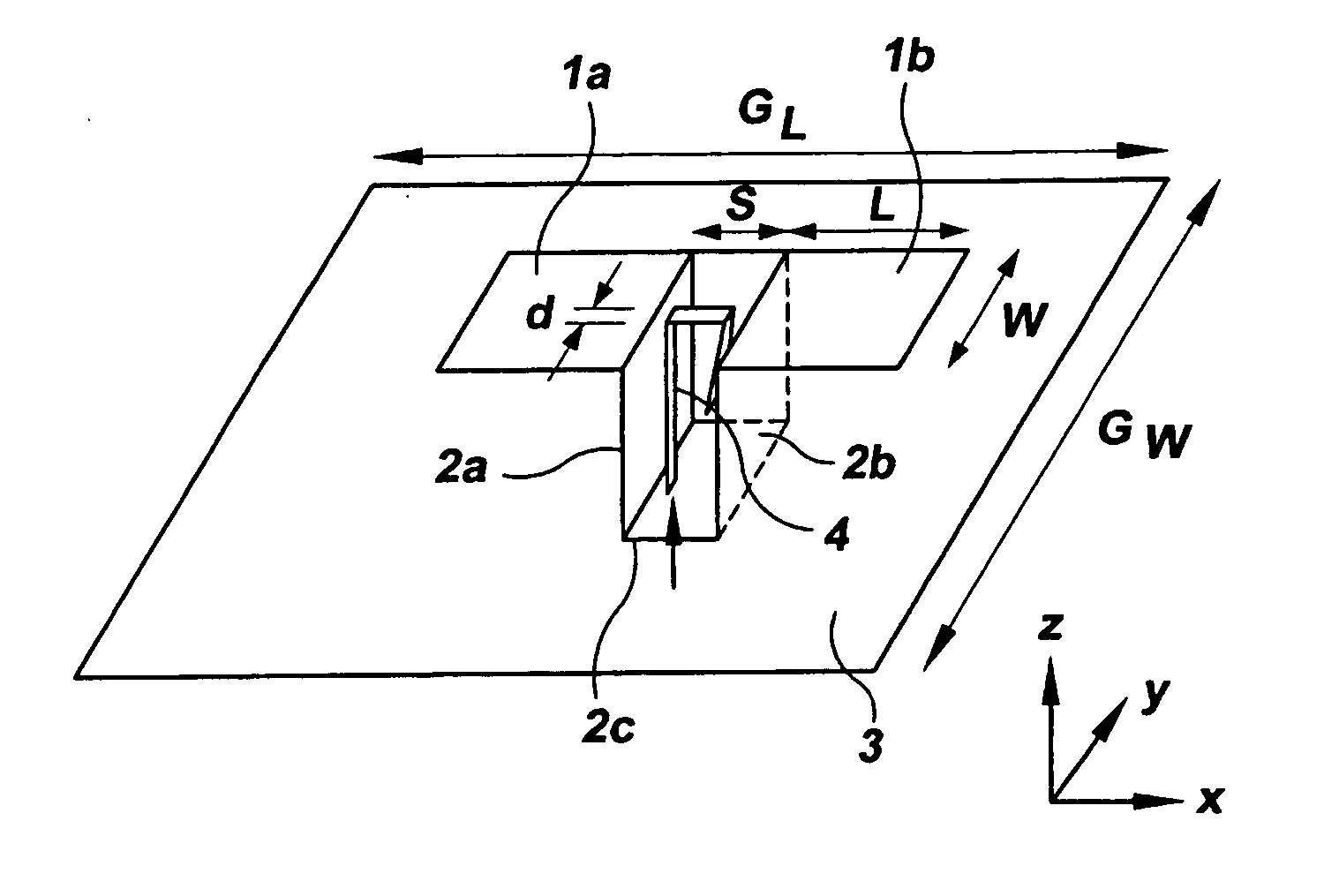
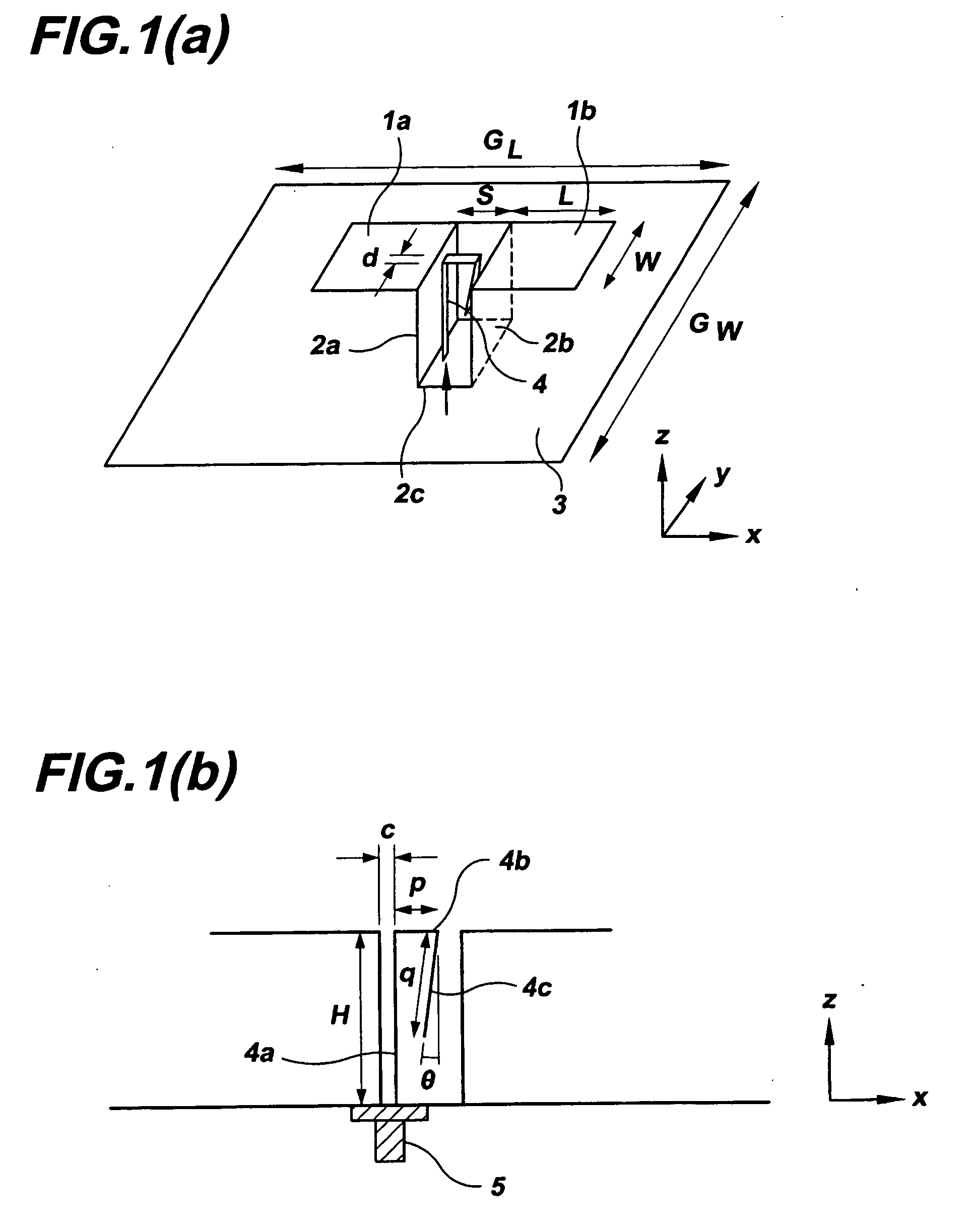
[0029] Referring firstly to FIG. 1 there is shown one example of a complementary wideband antenna according to an embodiment of the invention with FIG. 1 (a) being a perspective view and FIG. 1(b) a side view. In the embodiment of FIG. 1 the antenna comprises a horizontal rectangular planar dipole formed by dipole sections 1a and 1b connected to the open end of a vertically-oriented shorted patch antenna comprising vertical sections 2a, 2b and horizontal section 2c. A ground plane 3 is located beneath the antenna for back lobe reduction. In the embodiment of FIG. 1 the horizontal section 2c of the shorted patch antenna is an integral part of the ground plane 3 located between the vertical sections 2a, 2b but the section 2c could be an individual connecting section separate from the ground plane (see FIG. 9 below for examples). The function of the horizontal section 2c is to connect the vertical sections 2a, 2b so that they are electrically short-circuited. Vertical sections 2a, 2b a...


PUM


Abstract

A complementary wideband antenna includes a planar dipole formed of two dipole sections and a shorted patch antenna located between the dipole sections, the dipole sections being spaced above a ground plane. A variety of different feed probe designs can be used to excite the antenna. The complementary wideband antenna has electrical characteristics including low back radiation, low cross polarization, a symmetrical radiation pattern, and is stable in gain and radiation pattern shape over the frequency bandwidth.

Description

FIELD OF THE INVENTION [0001] This invention relates to a wideband antenna, and in particular to a complementary wideband antenna comprising a planar dipole and a shorted patch antenna. BACKGROUND INFORMATION [0002] The success of second generation (2G) mobile phones has motivated and enhanced the development of a wide range of wireless technologies, including for example 3G video phones, WiFi, WIMAX, ZigBee and Bluetooth. For cost effectiveness and space utilization wideband antennas that can accommodate several different communication systems are in high demand. In particular, antennas with unidirectional radiation patterns of various beam widths are of interest as they may be mounted on walls or vehicles without degrading their electrical characteristics and without affecting the aesthetics of the mounting bodies. [0003] There are a number of techniques available for implementing wideband antennas with a unidirectional radiation pattern. The first approach is to put a dipole in f...

Claims


Application Information

Patent Timeline
IPC IPC(8): H01Q9/16H01Q1/38
CPCH01Q9/0421H01Q9/285H01Q5/371H01Q21/28H01Q21/24
Inventor LUK, KWAI-MANWONG, HANG
Owner CITY UNIVERSITY OF HONG KONG
Learn More