Rear structure of vehicle provided with curtain air bag apparatus
a technology for rear structures and air bags, which is applied in the direction of vehicular safety arrangments, vehicle components, pedestrian/occupant safety arrangements, etc., can solve the problems of difficult to ensure and achieve the effect of smooth expansion and deployment of curtain air bags
- Summary
- Abstract
- Description
- Claims
- Application Information
AI Technical Summary
Benefits of technology
Problems solved by technology
Method used
Image
Examples
first embodiment
[0057] First, a first embodiment of the present invention will be described with reference to FIGS. 1 to 13.
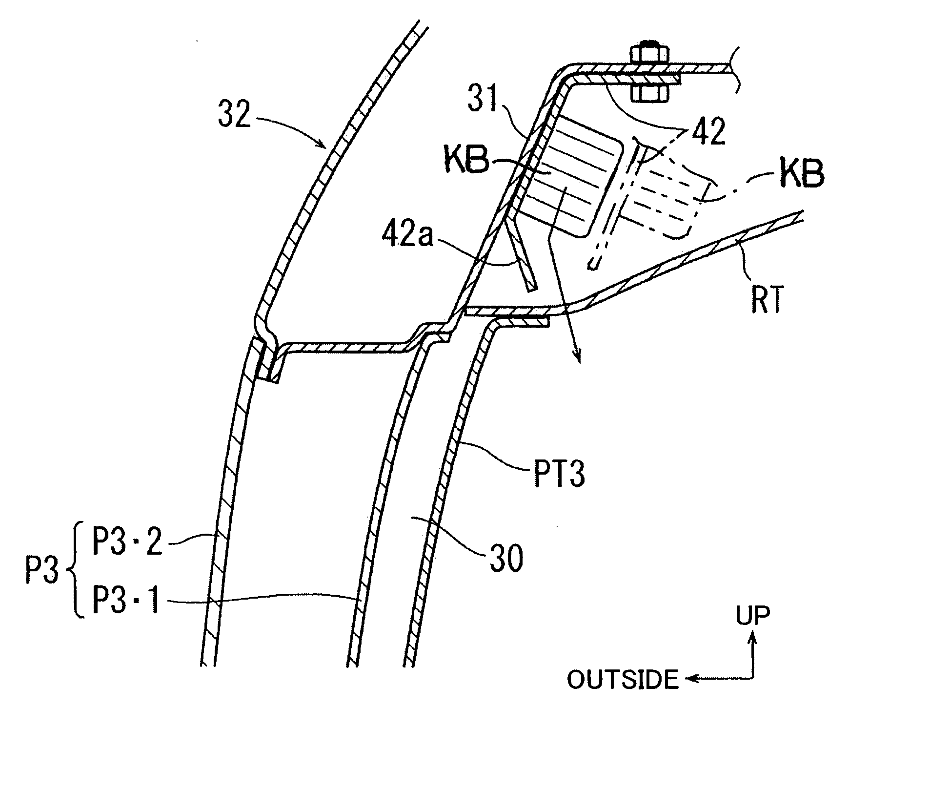
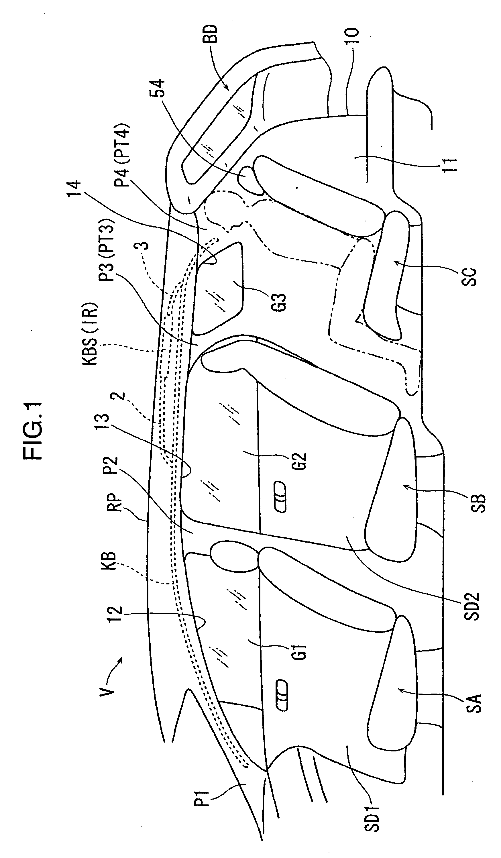
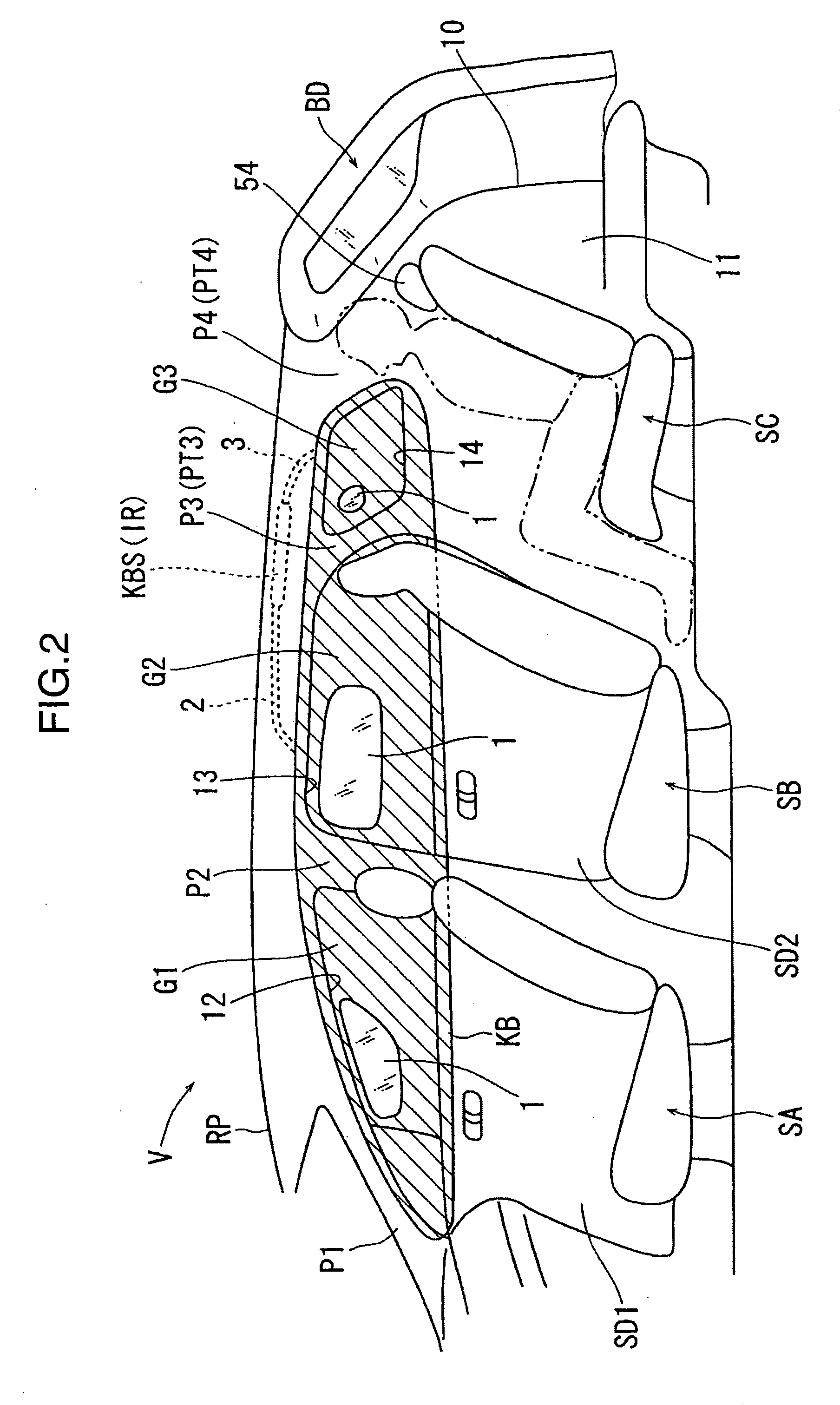
[0058] In FIGS. 1 and 2, a vehicle V includes a front seat SA, a second row seat SB disposed to the rear of the front seat SA, and a third row seat SC that is a specific seat disposed to the rear of the second row seat SB. A side door for the front seat SA is indicated by numeral SD1, and a side door for the second row seat SB is indicated by numeral SD2. The vehicle V includes, as pillars, in order from front to rear, an A pillar P1, a B pillar P2, a C pillar P3 as a middle pillar, and a D pillar P4 as a rear pillar. The area between left and right D pillars P4 is used for a rear opening 10 that is opened or closed by a back door BD, and through the rear opening 10, personal belongings are placed in or removed from a cargo compartment 11 to the rear of the third row seat SC.
[0059] The side door SD1 opens or closes a passenger opening 12 between the A pillar P1 and the B pil...
second embodiment
[0095] Next is a description of a second embodiment of the present invention with reference to FIGS. 25 to 27. The basic configuration of the second embodiment is the same as that of the first embodiment (see FIGS. 1 to 12), so the same constituent elements as in the first embodiment are given the same numerals and a duplicate description thereof is omitted here (also true for the third and fourth embodiments described below). Also, in the second embodiment as well, although a description with symbols is omitted in the drawings, same as in the first embodiment, the separation distance of the curtain air bag KB in a stored state from the side window glass G3 in the widthwise direction of the vehicle, in the portion along the rear edge of the side window glass G3, is set so as to be smaller than, among the portion along the upper edge of the side window glass G3, the portion in the vicinity of the middle pillar trim PT3 (see FIG. 13; L24). This is also true for the third and fourth em...
third embodiment
[0116] Next is a description of a third embodiment of the present invention with reference to FIGS. 33 to 37.
[0117] In the third embodiment, as shown in FIGS. 33 to 37, the outside end edge of the roof trim RT in the widthwise direction of the vehicle, between the pillar trim PT3 and the rear pillar trim PT4, protrudes slightly in the widthwise direction of the vehicle, but does not reach the side window glass G3. In the immediate vicinity of the side window glass G3, the roof side trim RST is provided extending in the front-rear direction along the upper edge of the side window glass G3. That is, the roof side trim RST is positioned to the outside of the roof trim RT in the widthwise direction of the vehicle. The roof side trim RST is set up in a case in which, when moving the roof trim RT from outside the vehicle to inside the vehicle cabin through a vehicle opening and installing the roof trim RT to the roof, the roof trim RT cannot be largely formed for a reason such as the ope...
PUM
 Abstract
Description
Claims
Application Information
 - R&D
- Intellectual Property
- Life Sciences
- Materials
- Tech Scout
- Unparalleled Data Quality
- Higher Quality Content
- 60% Fewer Hallucinations
Browse by: Latest US Patents, China's latest patents, Technical Efficacy Thesaurus, Application Domain, Technology Topic, Popular Technical Reports.
© 2025 PatSnap. All rights reserved.Legal|Privacy policy|Modern Slavery Act Transparency Statement|Sitemap|About US| Contact US: help@patsnap.com


