Safety switch for a moveable guard door

Inactive Publication Date: 2007-09-06
PILZ (COMPANY)
View PDF29 Cites 30 Cited by
  • Summary
  • Abstract
  • Description
  • Claims
  • Application Information

AI Technical Summary

Benefits of technology

[0010] It is another object to provide for a safety switch with a guard locking function which can be realized in a simple and cost-effective manner.
[0042] The integration of an emergency stop pushbutton and / or an acknowledge pushbutton in the novel safety switch contributes to a further reduction in the installation complexity. An emergency stop pushbutton serves the purpose of bringing a monitored machine or system in a hazardous situation rapidly into a safe state manually. The integration of such a pushbutton in the novel safety switch is particularly advantageous since the safety switch does not allow for emergency shutdown of the machine or system by itself owing to the guard locking function. The integration of an acknowledge pushbutton makes it possible to manually acknowledge closure of a guard door, which can be used in an advantageous manner for bringing the machine or system into operation again.

Problems solved by technology

The machine may be, for example, a robot, a machine tool having a rapidly rotating spindle, a transportation or conveying system, a press or another machine or system whose operation represents a hazard to people located in the working area of the machine.
There is a large number of machines and systems which represent a hazard for a certain amount of time even after they have been shut down, for example because the machine or system is still running down.
The known safety switch therefore has the disadvantage that the guard door and the frame need to be aligned very precisely with respect to one another so that the activator can engage in the activator receptacle.
It is thus difficult to install this known safety switch.
Problems also result if the guard door drops over the course of time, with the result that the installation tolerances are no longer maintained.
In this case, the guard door can no longer be closed properly.
This known safety switch also requires tight installation tolerances.

Method used


Image

  • Safety switch for a moveable guard door
  • Safety switch for a moveable guard door
  • Safety switch for a moveable guard door

Examples


Embodiment Construction

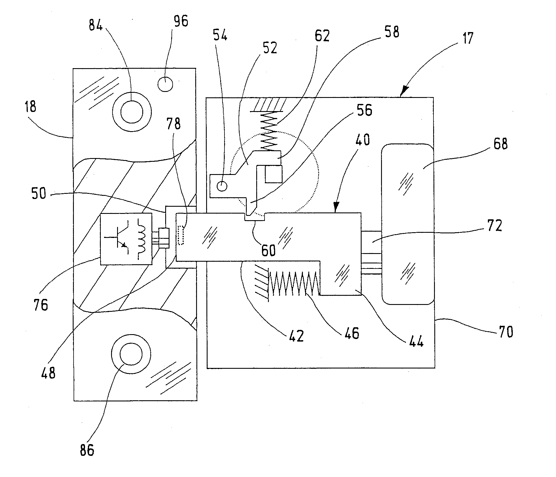
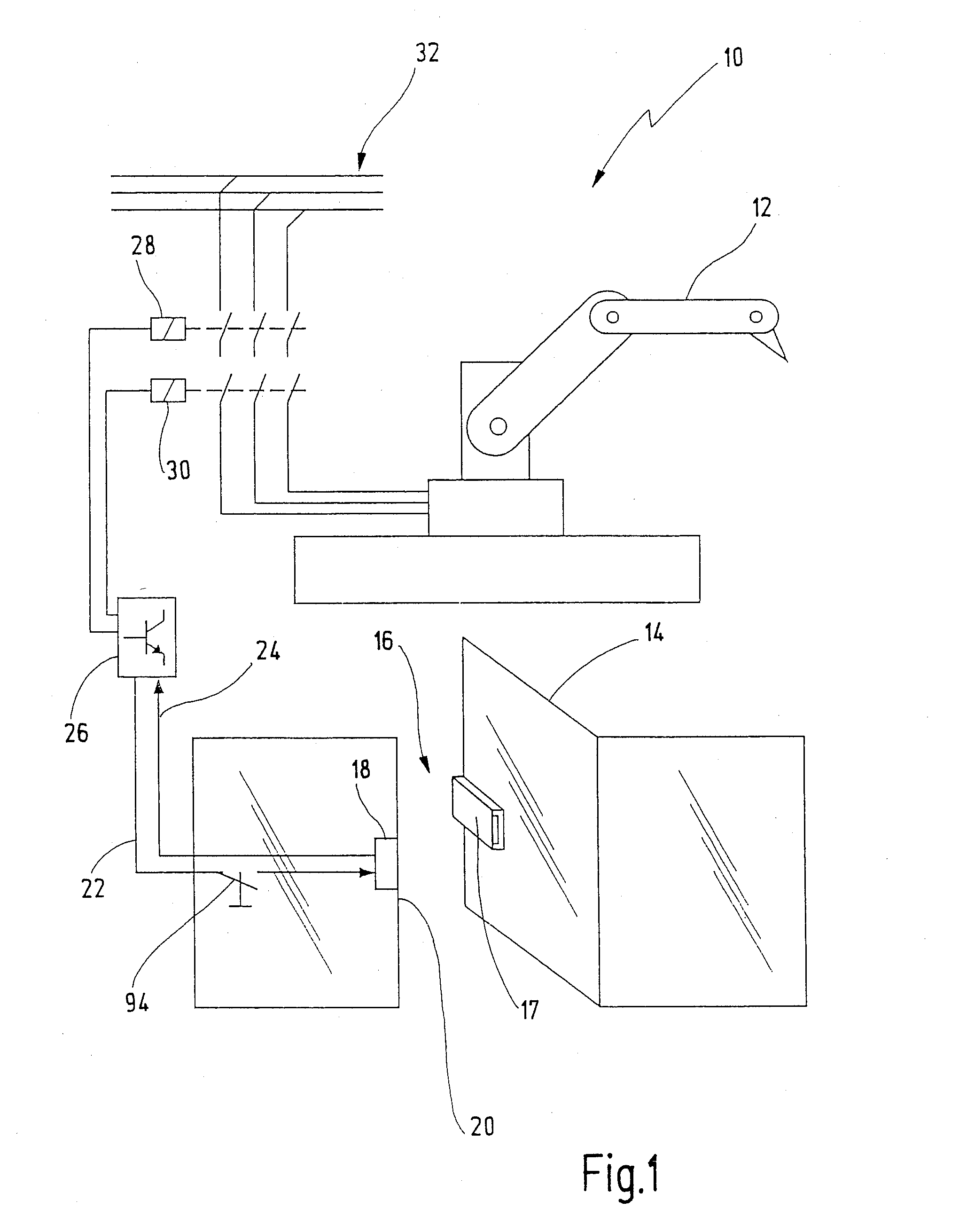
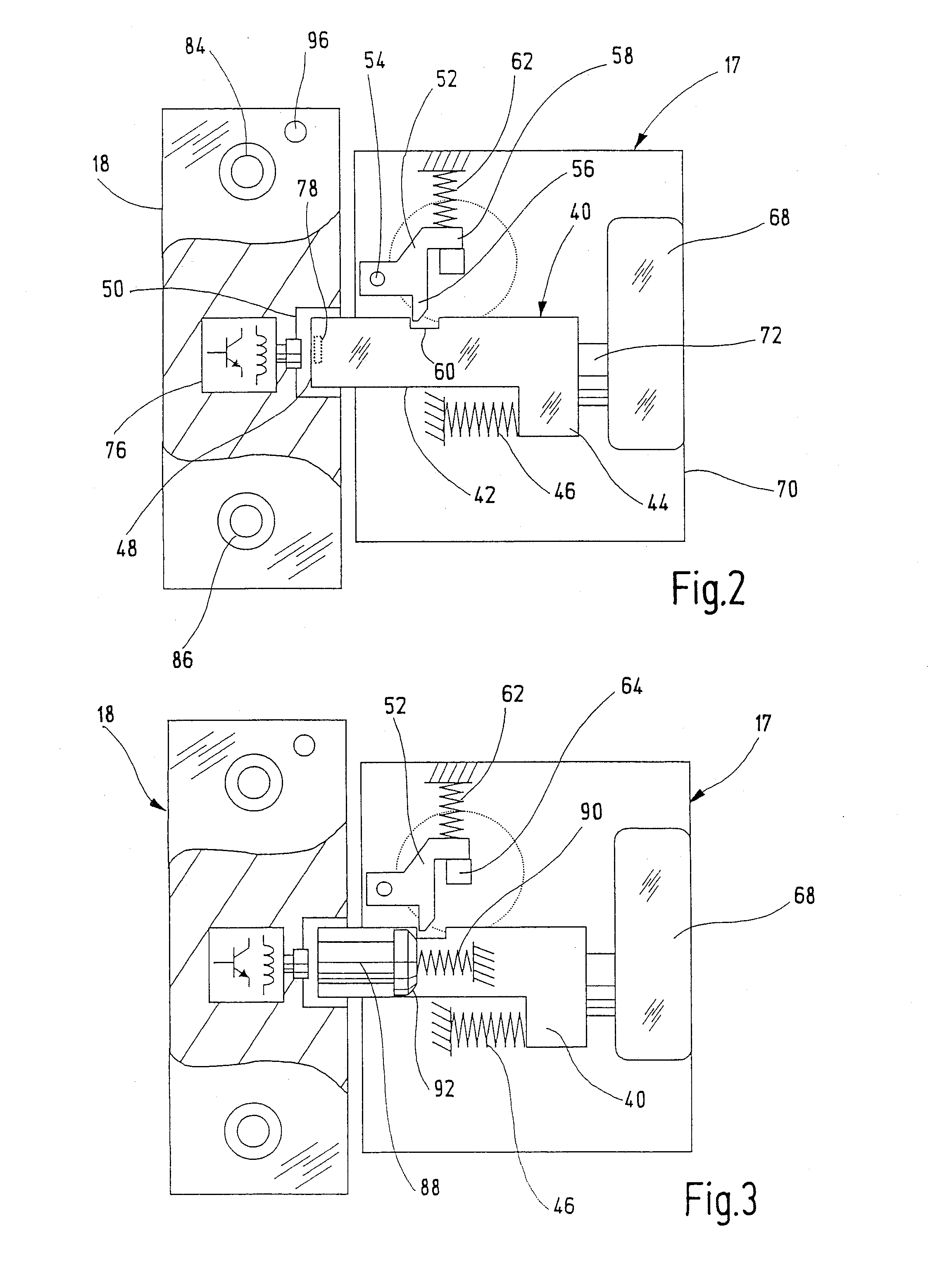
[0050] In FIG. 1, an apparatus having the novel safety switch is denoted in its entirety by the reference numeral 10. The apparatus 10 in this case contains a robot 12, whose working area is secured by means of a guard door 14. A safety switch 16 in accordance with the present invention is arranged on the guard door 14. The safety switch 16 contains a door part 17, which is fixed to the moveable guard door 14, and a frame part 18, which rests on a mating door piece 20. In the embodiment illustrated, the mating door piece 20 is a stationary stop for the guard door 14. In the other embodiments, the mating door piece 20 may be a second door leaf of a two-part guard door.

[0051] The frame part 18 is connected to a safety switching device 26 via two lines 22, 24. The safety switching device 26 is, for example, a safety switching device from the PNOZ® series, which is marketed by the Applicant of the present invention. These safety switching devices are multi-channel-redundant safety swit...


PUM


Abstract

There is disclosed a safety switch for generating an enable signal as a function of the position of a moveable guard door. The safety switch comprises a door part and a frame part. The door part has an activator, which can be displaced between a first and a second position. The frame part has a cutout, in which the activator can engage in the second position. A locking element is arranged on the door part in order to lock the activator in the second position. A sensor is designed to detect at least one of the positions of the activator in order to generate the enable signal as a function thereof.

Description

BACKGROUND OF THE INVENTION [0001] The present invention relates to a safety switch for generating an enable signal as a function of the position of a moveable guard door, and more particularly to a safety switch of this kind having a locking element designed to lock the guard door in the closed position. [0002] Safety switches of this kind may also be referred to as interlock devices with guard locking. They are used on guard doors, guard flaps or the like, which are intended to prevent access to an automated machine or system as long as the machine or system is in a hazardous state. The machine may be, for example, a robot, a machine tool having a rapidly rotating spindle, a transportation or conveying system, a press or another machine or system whose operation represents a hazard to people located in the working area of the machine. The safety switches can be used as signaling devices, by means of which a control device can identify the closed state of the guard door. The contro...

Claims


Application Information

Patent Timeline
IPC IPC(8): E05B47/00H01H9/00
CPCE05B15/101E05B15/102E05B17/10E05B41/00F16P3/10E05B63/04E05B2047/0069E05B2047/0086E05B47/0046Y10S292/31Y10T292/18Y10T292/0999Y10T70/713Y10T70/7102Y10T292/1021Y10T70/5761Y10T292/57Y10T292/1003Y10T292/1031Y10T70/8027Y10T70/7107Y10T70/7062Y10T292/558
Inventor PULLMANN, JURGENRUPP, ROLANDVEIT, ANDREASEICHINGER, PETER
Owner PILZ (COMPANY)
Why Eureka
Try Eureka