Air Conditioning Apparatus
- Summary
- Abstract
- Description
- Claims
- Application Information
AI Technical Summary
Benefits of technology
Problems solved by technology
Method used
Image
Examples
embodiment 1
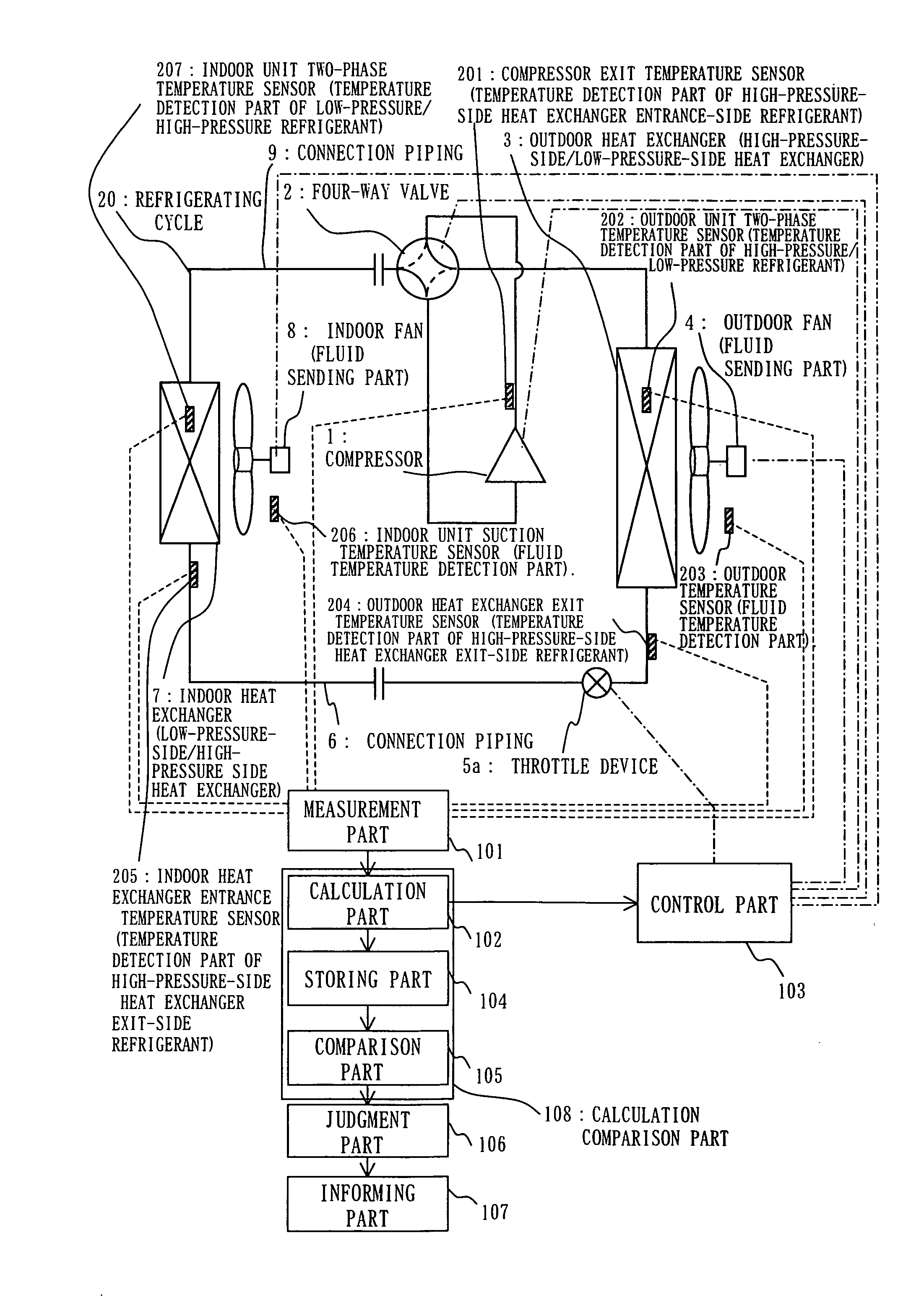
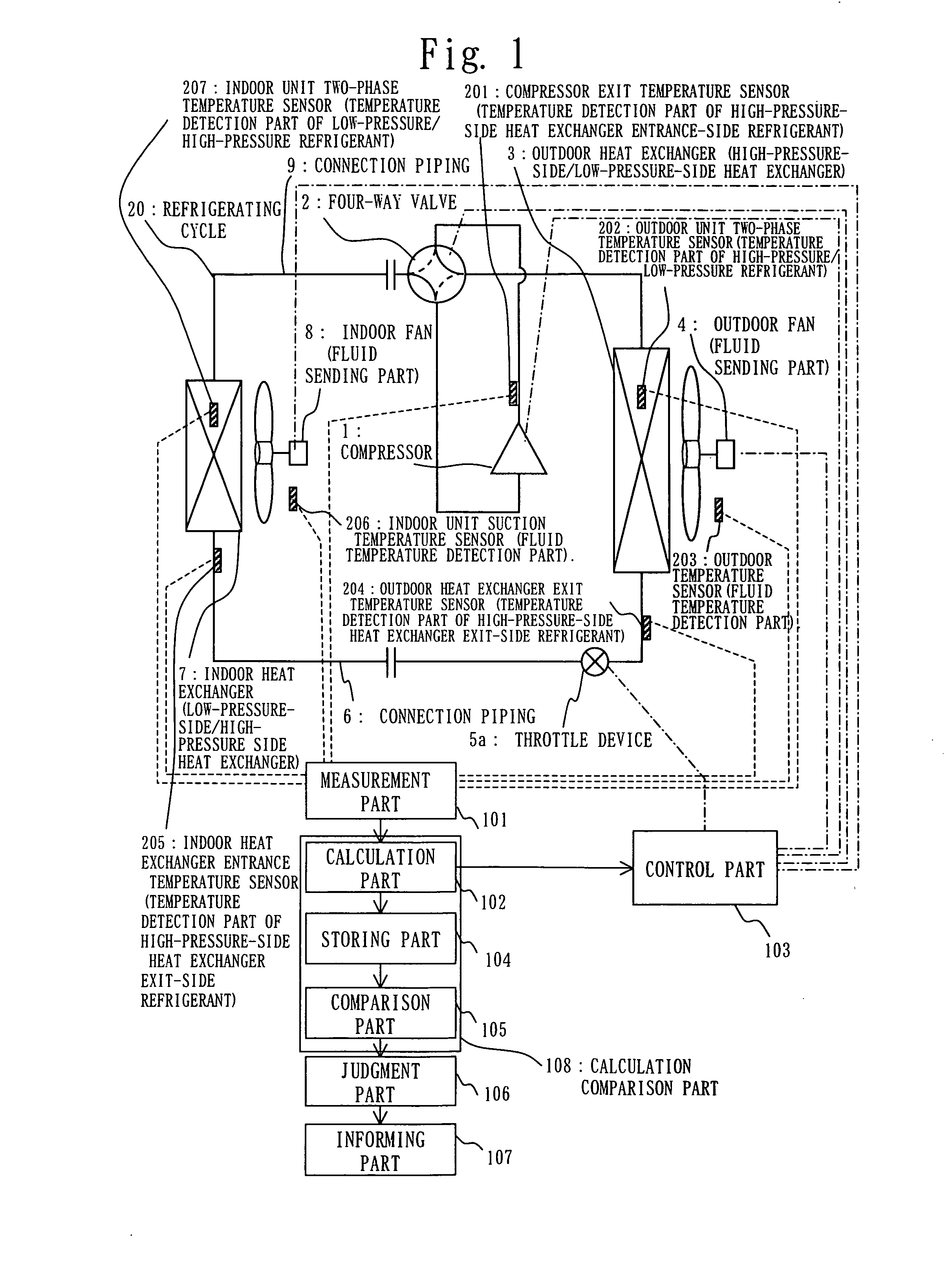
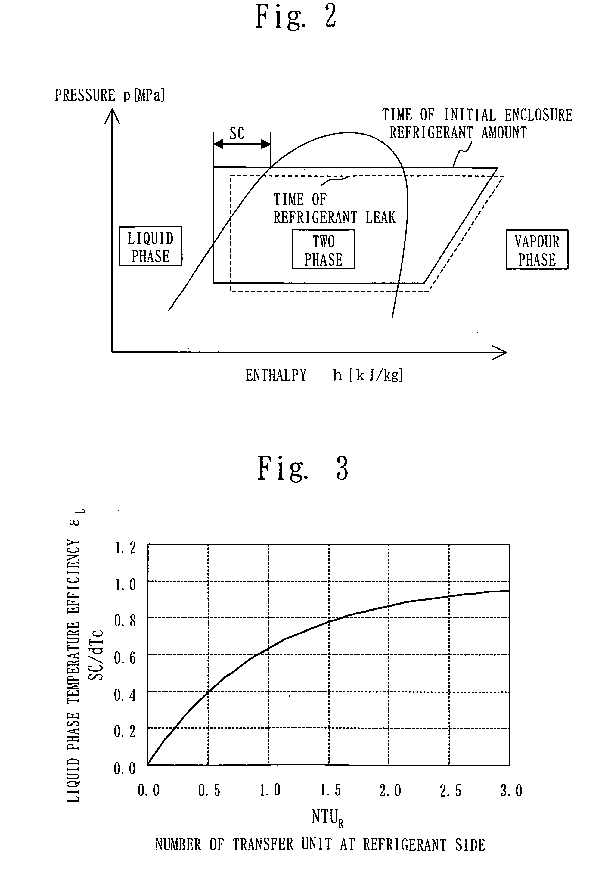
[0065] FIGS. 1 to 6 show Embodiment 1, FIG. 1 illustrates a structure of an air conditioning apparatus, FIG. 2 is a p-h diagram at the time of refrigerant leak, FIG. 3 shows a relation between SC / dTc and NTUR, FIG. 4 shows a relation between SC / dTc and NTUR at the time of refrigerant leak, FIG. 5 is an operation flowchart, and FIG. 6 illustrates a calculation method of SC at a supercritical point.
[0066] As shown in FIG. 1, there are provided an outdoor unit, an indoor unit, and a refrigerating cycle 20. The outdoor unit includes a compressor 1, a four-way valve 2 which is switched from / to the state of cooling operation described as the solid line and the state of heating operation described as the broken line, an outdoor heat exchanger 3 which functions as a high-pressure-side heat exchanger (condenser) at cooling operation time and as a low-pressure-side heat exchanger (evaporator) at a heating operation time, an outdoor fan 4 which supplies air, being an example of fluid, to the ...
embodiment 2
[0113] Embodiment 2 will be explained with reference to a figure. The same signs are assigned to the parts being the same as those in Embodiment 1, and detailed explanation is omitted.
[0114]FIG. 7 shows Embodiment 2, and illustrates a structure of an air conditioning apparatus. In the figure, a receiver 10 that accumulates a surplus refrigerant amount being the difference of required refrigerant amounts at the cooling operation and the heating operation is provided behind the throttle device 5a (an upstream side throttle device), and a throttle device 5b (a downstream side throttle device) is added at the exit of the receiver in the structure, which is the air conditioning apparatus of the type that needs no additional refrigerant at a spot.
[0115] Since there is the portion where a liquid refrigerant stays in the refrigerating cycle, an operation (a special operation mode) for storing the surplus refrigerant in the receiver in the outdoor heat exchanger 3 is performed by the opera...
embodiment 3
[0117] Embodiment 3 will be explained with reference to a figure. The same signs are assigned to the parts being the same as those in Embodiment 1, and detailed explanation is omitted.
[0118]FIGS. 8 and 9 show Embodiment 3, FIG. 8 illustrates a structure of an air conditioning apparatus, and FIG. 9 illustrates another structure of the air conditioning apparatus.
[0119] As shown in FIG. 8, an accumulator 11 is provided at the suction portion of the compressor, and a surplus refrigerant amount being the difference of required refrigerant amounts at the cooling operation and the heating operation is accumulated in the accumulator 11, which is the air conditioning apparatus of the type that needs no additional refrigerant at a spot.
[0120] In the case of there being the accumulator 11, since it is necessary to perform an operation not to accumulate a liquid refrigerant in the accumulator 11, the throttle device 5a is throttled by the indoor heat exchanger 7 in order to have enough super...
PUM
 Abstract
Description
Claims
Application Information
 - R&D
- Intellectual Property
- Life Sciences
- Materials
- Tech Scout
- Unparalleled Data Quality
- Higher Quality Content
- 60% Fewer Hallucinations
Browse by: Latest US Patents, China's latest patents, Technical Efficacy Thesaurus, Application Domain, Technology Topic, Popular Technical Reports.
© 2025 PatSnap. All rights reserved.Legal|Privacy policy|Modern Slavery Act Transparency Statement|Sitemap|About US| Contact US: help@patsnap.com


