Positional information detecting method and device

a position information and detection method technology, applied in the direction of noise figure or signal-to-noise ratio measurement, distance measurement, instruments, etc., can solve the problems of reducing the reliability of measurement results increasing complexity and cost of distance measuring devices, and prone to propagating tone burst signals. to achieve the effect of improving the resolution of position information

Inactive Publication Date: 2007-08-30
DENSO CORP
View PDF1 Cites 14 Cited by
  • Summary
  • Abstract
  • Description
  • Claims
  • Application Information

AI Technical Summary

Benefits of technology

[0017]In view of the background, an object of at least one aspect of the present invention is to improve the resolution of positional information of a target, such as a distance thereof, to be detected using a tone burst signal.

Problems solved by technology

This may require an A / D converter and the like, which are operable at a high sampling frequency, causing the distance measuring device to increase in complexity and in cost.
In addition, in the above-mentioned method of determining the detection time based on the monitored level of the detected tone burst signal, the accuracy of determining the detection time may be susceptible to the strength of the propagating tone burst signal, in other words, the level of the detected tone burst signal and / or noise superimposed on the detected tone burst signal.
This may reduce the reliability of measurement results of the distance measuring device.
Specifically, if the tone burst signal has not reached the detector yet, but a noise signal with large amplitude enters the detector, the detector would erroneously determine that the tone burst signal has already reached the detector upon entry of the noise signal.
In addition, if the tone burst signal has already reached the detector, but a noise signal out of phase with the tone burst signal enters the detector so that it reduces the level thereof, the detector would also erroneously determine that the tone burst signal has not reached the detector yet.

Method used


Image

  • Positional information detecting method and device
  • Positional information detecting method and device
  • Positional information detecting method and device

Examples


Embodiment Construction

[0033]An embodiment of the present invention will be described hereinafter with reference to the accompanying drawings.

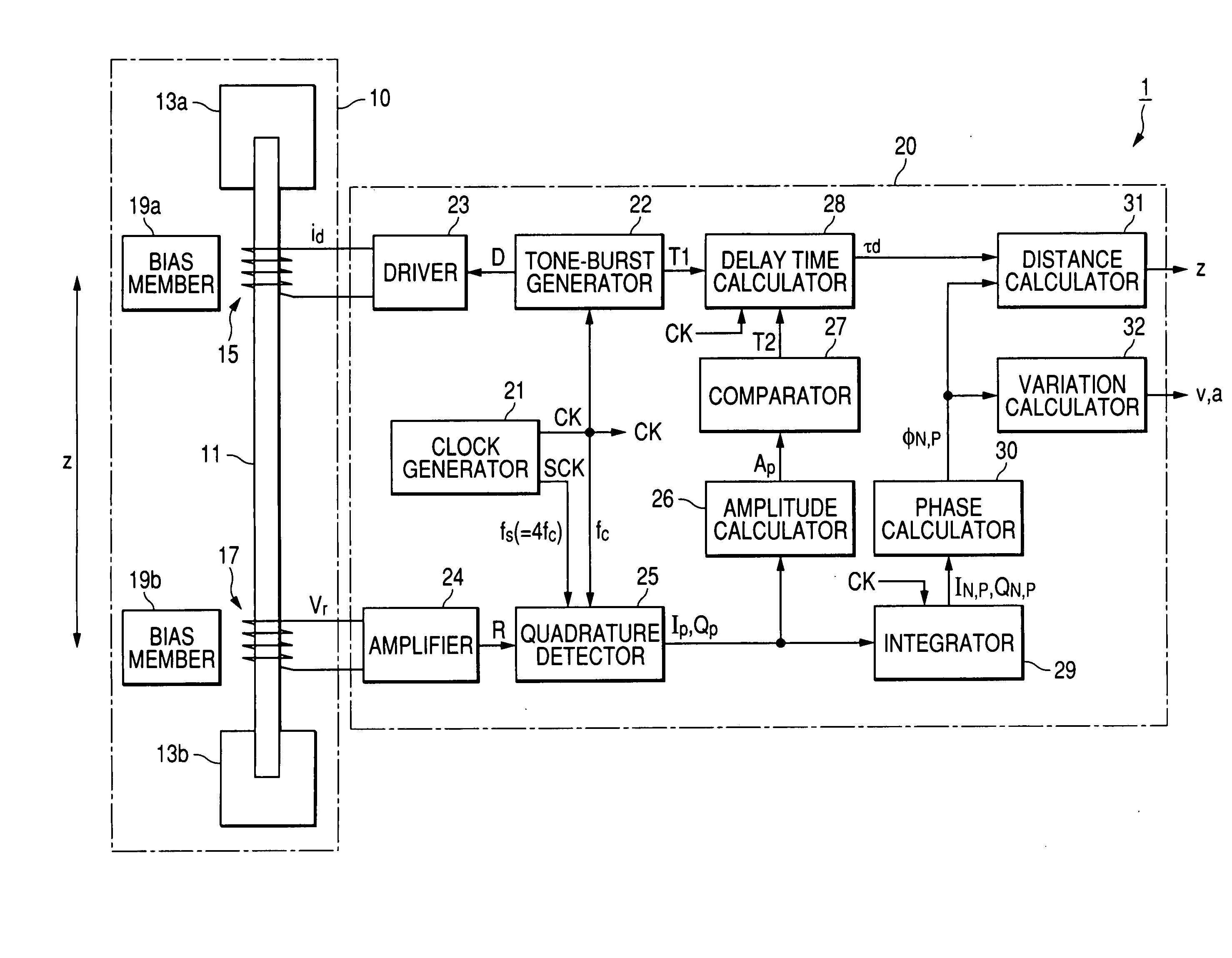
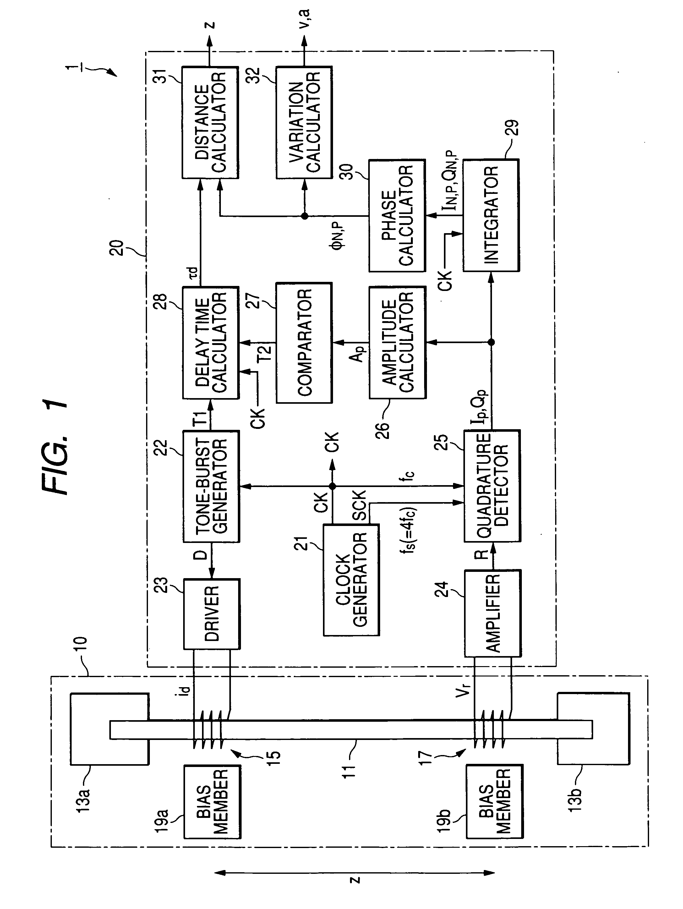
[0034]Referring to the drawings, in which like reference characters refer to like parts in several views, FIG. 1 illustrates an example of the overall structure of a position sensor 1 according to the embodiment to which the present invention is applied.

[0035]As illustrated in FIG. 1, the position sensor 1 is provided with a sensor module 10 designed to use magnetoelastic-wave propagation to measure positional information of a target. The position sensor 1 is also provided with a signal-processing unit 20 operative to drive the sensor module 10 and to process signals sensed by the sensor module 10 driven thereby.

[0036]The sensor module 10 is composed of:

[0037]an amorphous wire 11 serving as a medium for generating magnetoelastic waves and for propagating them;

[0038]a pair of wire holders 13a and 13b that hold both tips of the amorphous wire 11, respectively;

[0039]an...


PUM


Abstract

In a positional information detecting device, a tone-burst signal propagating unit causes a tone-burst signal to propagate through a path. The tone-burst signal is composed of a continuous wave train, the continuous wave train including a plurality of cycles of a constant frequency. A detecting unit detects, at a predetermined position in the path, the tone-burst signal propagating through the path every one cycle of the tone-burst signal to measure a propagation delay time based on the detected signal. The propagation delay time represents a period for which the tone-burst signal has propagated through the path. A phase obtaining unit obtains a phase of the detected signal. A positional information obtaining unit obtains positional information associated with the predetermined position based on the measured propagation delay time and the obtained phase of the detected signal.

Description

CROSS REFERENCE TO RELATED APPLICATIONS[0001]This application is based on Japanese Patent Application 2006-048533 filed on Feb. 24, 2006. This application claims the benefit of priority from the Japanese Patent Application, so that the descriptions of which are all incorporated herein by reference.FIELD OF THE INVENTION[0002]The present invention relates to positional information detecting methods and devices, which are designed to detect positional information using a tone burst signal that is composed of a continuous wave train consisting of several cycles of a constant frequency over a constant period.BACKGROUND OF THE INVENTION[0003]Distance measuring technique using an ultrasonic wave propagative in the atmosphere and / or a liquid or an elastic wave propagative in a solid is conventionally known, an example of which is disclosed in Japanese Unexamined Patent Publication.[0004]Specifically, such distance measuring technique can measure the distance of a point from which the waves...

Claims


Application Information

Patent Timeline
Patent Type & Authority Applications(United States)
IPC IPC(8): G01B21/02G01R13/00
CPCG01S11/14G01B17/00
Inventor WATANABE, TAKAMOTOMASUDA, SUMIO
Owner DENSO CORP
Why Eureka
Try Eureka