
Equalizer with controllably weighted parallel high pass and low pass filters and receiver including such an equalizer

Active Publication Date: 2007-08-30
LATTICE SEMICON CORP
View PDF3 Cites 76 Cited by
  • Summary
  • Abstract
  • Description
  • Claims
  • Application Information

AI Technical Summary

Benefits of technology

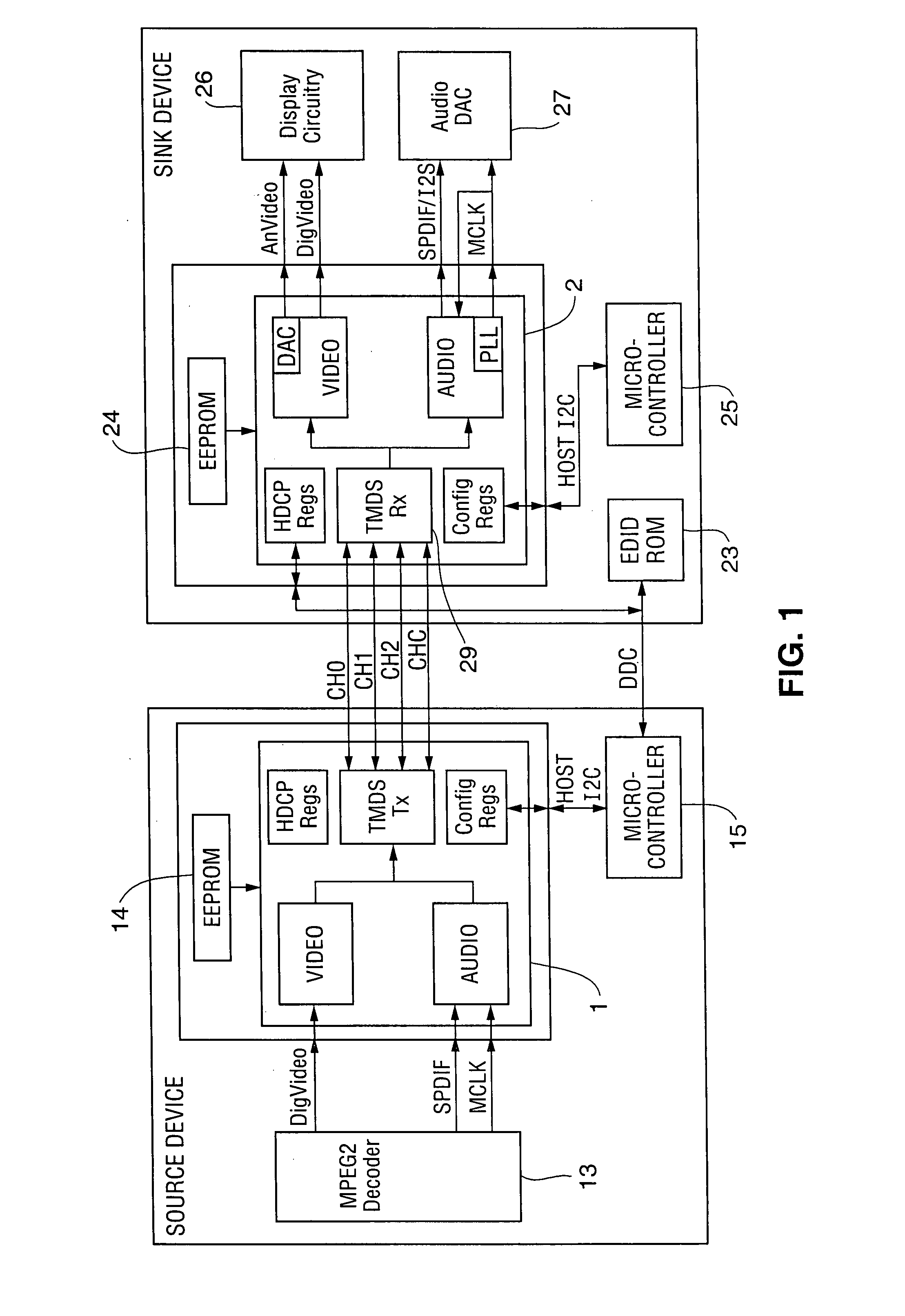
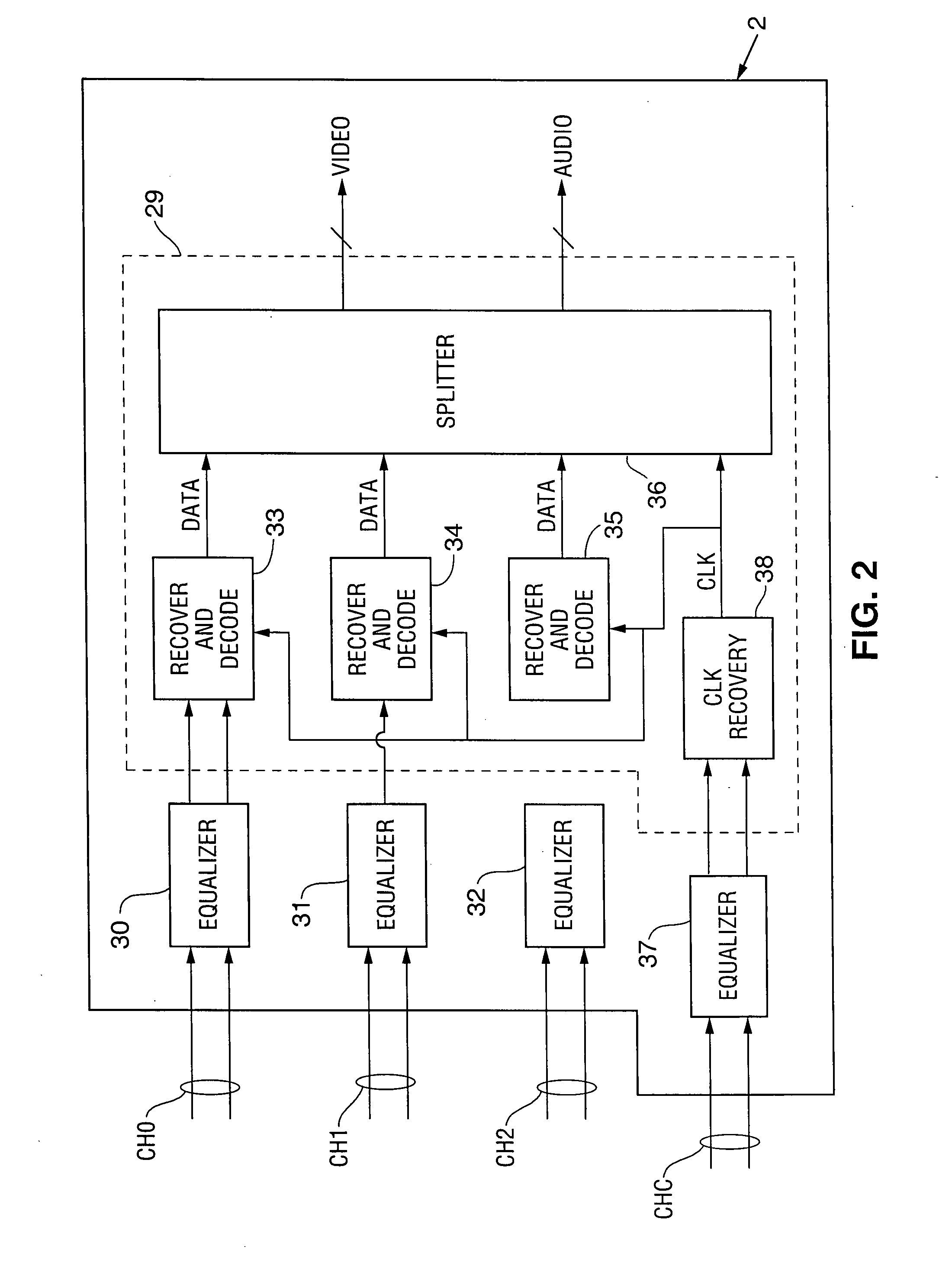
[0010] In a class of embodiments, the invention is a receiver configured to equalize a signal, indicative of video data (or other data) having a maximum data rate of at least 1 Gb/s, that has propagated over a serial link to the receiver. For example, the receiver can include equalizers that filte

Problems solved by technology

The cable filter can cause inter-symbol interference (ISI).
When a receiver including such a conventional equalizer is implemented using CMOS technology, adjustment of the equalizer is impractical when the data rate exceeds 1 Gb/s (1 Gigabit per second) because the transconductance (gm) for the CMOS transistor circuitry is relatively small and any additional switch or passive element in the equalizer would have a large adverse effect on equa

Method used


Image

  • Equalizer with controllably weighted parallel high pass and low pass filters and receiver including such an equalizer
  • Equalizer with controllably weighted parallel high pass and low pass filters and receiver including such an equalizer
  • Equalizer with controllably weighted parallel high pass and low pass filters and receiver including such an equalizer

Examples


Embodiment Construction

[0018] The term “transmitter” is used herein in a broad sense to denote any device capable of encoding data and transmitting the encoded data over a link (and optionally also performing additional functions, which can include encrypting the data to be transmitted and other operations related to encoding, transmission, or encryption of the data). The term “receiver” is used herein in a broad sense to denote any device capable of receiving and decoding data that has been transmitted over a link (and optionally also performing additional functions, which can include decrypting the received data and other operations related to decoding, reception, or decryption of the received data). For example, the term transmitter can denote a transceiver that performs the functions of a receiver as well as the functions of a transmitter.

[0019] In typical embodiments, the invention is a receiver configured to be coupled to a serial link having at least one video channel. The receiver includes equali...


PUM


Abstract

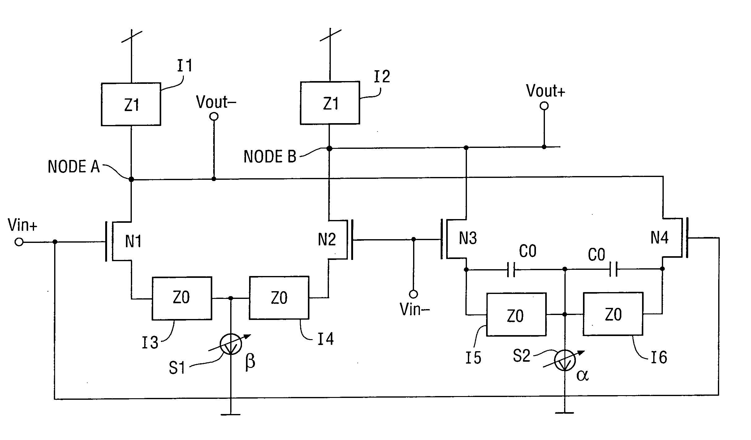
An adjustable equalizer that includes a first branch including a low pass filter (LPF) and having a variable gain (β), and a second branch including a high pass filter (HPF) and having another variable gain (α). Outputs of the branches in response to an input signal are summed to produce an equalized output. The equalizer can be implemented using CMOS technology so that the gain parameters β and α are independently adjustable and the equalizer is capable of equalizing an input indicative of data having a maximum data rate of at least 1 Gb/s. Typically, the inventive equalizer is embodied in a receiver for use in equalizing a signal, indicative of video or other data, that has propagated over a serial link to the receiver. In some embodiments useful for equalizing a differential input signal, the equalizer includes two differential pairs of MOS transistors and a controllable current source determines the tail current for each differential pair. The current sources are independently controllable. When the equalizer includes purely resistive impedances Z0 and Z1, the equalizer's transfer function is Z1/Z0.(β+α·(1+s·C0·Z0)), where β is a gain parameter determined by the tail current of one differential pair and α is a gain parameter determined by the tail current of the other differential pair.

Description

TECHNICAL FIELD OF THE INVENTION [0001] The invention pertains to circuitry for equalizing signals (e.g., high frequency signals indicative of data having data rate greater than 1 Gb / s) that have been received after propagating over a link. Typically, the inventive equalization filter is implemented using CMOS technology and is included in a receiver coupled to a serial link to receive a signal indicative of data transmitted at a high data rate (e.g., above 1 Gb / s), to perform equalization needed for reliable data recovery. BACKGROUND OF THE INVENTION [0002] The transmission of signals indicative of data (e.g., signals indicative of video or audio data) to a receiver over a link degrades the data, for example by introducing time delay error (sometimes referred to as jitter) to the data. In effect, the link applies a filter (sometimes referred to as a “cable filter”) to the signals during propagation over the link. The cable filter can cause inter-symbol interference (ISI). [0003] Eq...

Claims


Application Information

Patent Timeline
IPC IPC(8): H03H7/30H04B1/10
CPCH04L25/03159H04L63/04H04L2025/03522H04L2025/03356H04L63/166
Inventor LEE, DONGYUN
Owner LATTICE SEMICON CORP
Learn More