Liquid ejection method, liquid ejection apparatus, double-side printing method and image recording apparatus for double-side printing

a liquid ejection and printing method technology, applied in the direction of printing, typewriters, other printing apparatus, etc., can solve the problems of nozzle blockage, nozzle surface solidification, nozzle contamination, etc., to prevent the occurrence of nozzle surface contamination and prevent contamination on the nozzle surface

Inactive Publication Date: 2007-08-30
FUJIFILM CORP
View PDF6 Cites 25 Cited by
  • Summary
  • Abstract
  • Description
  • Claims
  • Application Information

AI Technical Summary

Benefits of technology

[0053]It is possible to prevent the occurrence of nozzle surface contamination according to the present invention. Furthermore, it is also possible to carry out double-side printing while preventing contamination on the nozzle surfaces of the heads.

Problems solved by technology

Moreover, there is a possibility that the correct operation of the apparatus is obstructed because of the deposition of the ink mist onto the interior of the apparatus.
In this case, if contamination on the nozzle surfaces occurs between the head for ejecting the treatment liquid and the head for ejecting the ink (the nozzle surface of the head for the treatment liquid or the nozzle surface of the head for the ink is contaminated by a mist generated from the other head), then the ink solidifies on the nozzle surface and the nozzles become blocked, and ejection defects may thus arise.
Moreover, this inkjet recording apparatus uses ink which is subjected to an aggregation reaction, in order to prevent bleeding and print-through, and the like, of the ink deposited on the paper, which may be problematic especially in the case of double-side printing.
The spaces for the mist recovery devices hence need to be provided, and therefore, the recording apparatus becomes large in size.
Moreover, when the distance between the heads is increased, displacement of the dot positions is liable to occur; therefore, it becomes difficult to achieve high image quality.
Furthermore, in order to achieve high image quality, highly precise conveyance is necessary, and accordingly the costs can be increased.
In the technology described in Japanese Patent Application Publication No. 2003-11334, it is necessary to dispose ultraviolet light radiation units on either side of the head, and therefore space for this installation is required.
Thus, in each of the related art cases described above, there are obstacles, such as increased size of the apparatus, degradation of image quality due to increase in the distance between the heads, and increased costs as a result of the need for high-precision conveyance.
However, in a line-type of semi-fixed head, since depositing position errors become more readily recognizable in comparison with a shuttle type of head, then the effects of contamination are very marked.
This maintenance action requires time and labor, and moreover, the productivity declines due to the increase in the frequency of maintenance.
In a case where liquids (reaction-liquids) of a two-liquid reaction type are ejected, it is difficult to remove the liquids that are hardened due to the curing reaction caused by contamination between the two liquids even if the maintenance action is performed, and moreover, ejection failures may arise due to curing in the nozzle units.
In the related art method which recovers ink mist as described above, it is difficult to prevent contamination between heads sufficiently.
Therefore, contamination can occur between the heads, leading to deterioration of the image.
In particular, in cases of using reactive ink, contamination on the nozzle surface of the head occurs and the ink becomes cured, leading to blocking of the nozzles.
If the Y ink mist deposits onto the nozzle surface of the head K, then an aggregation reaction occurs between the Y ink and the K ink, thus leading to the occurrence of nozzle blockages, which are the cause of image deterioration.
Moreover, the technology described in Japanese Patent Application Publication No. 2005-67051 does not take account of the occurrence of contamination between the heads.

Method used


Image

  • Liquid ejection method, liquid ejection apparatus, double-side printing method and image recording apparatus for double-side printing
  • Liquid ejection method, liquid ejection apparatus, double-side printing method and image recording apparatus for double-side printing
  • Liquid ejection method, liquid ejection apparatus, double-side printing method and image recording apparatus for double-side printing

Examples


first embodiment

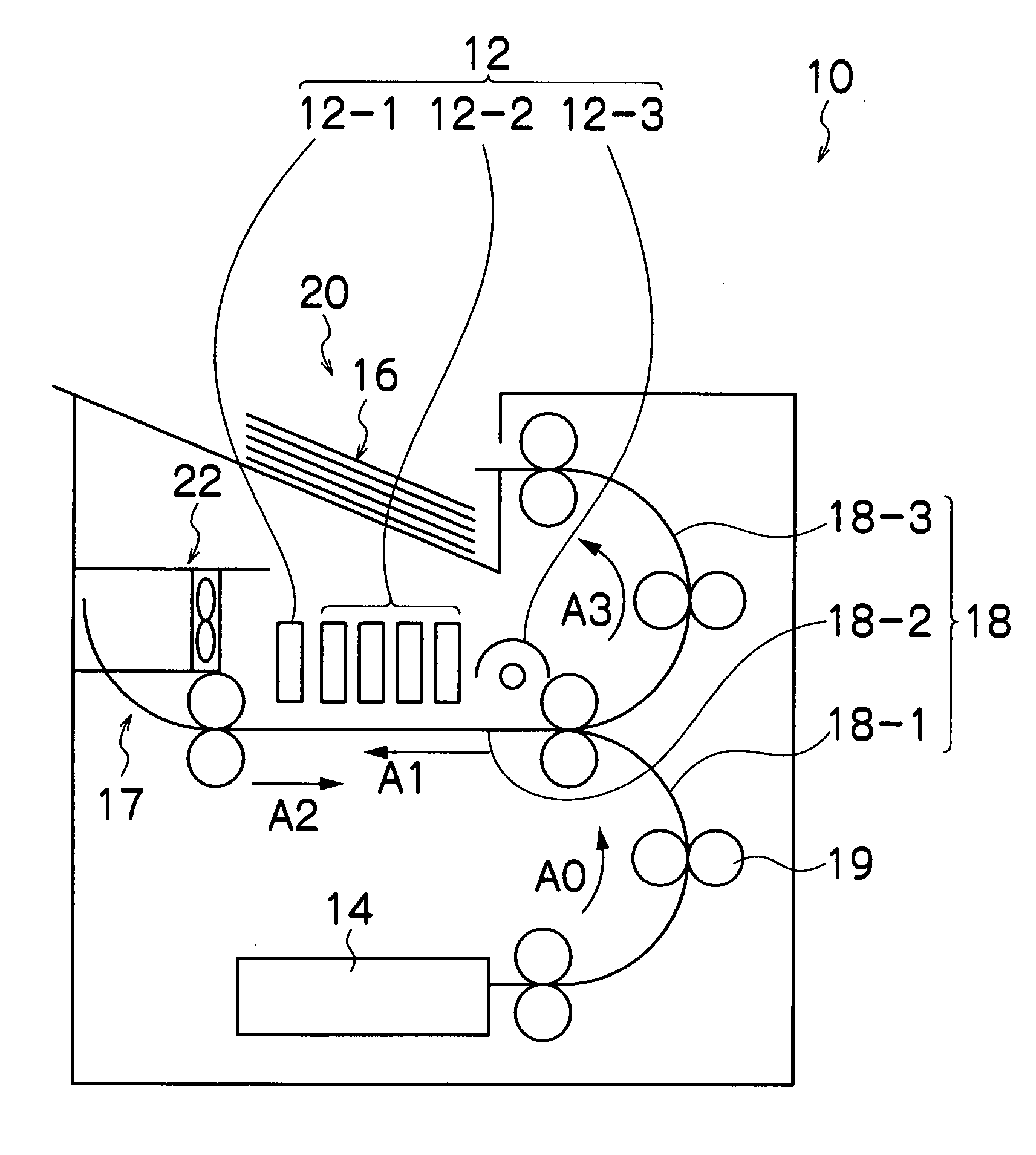
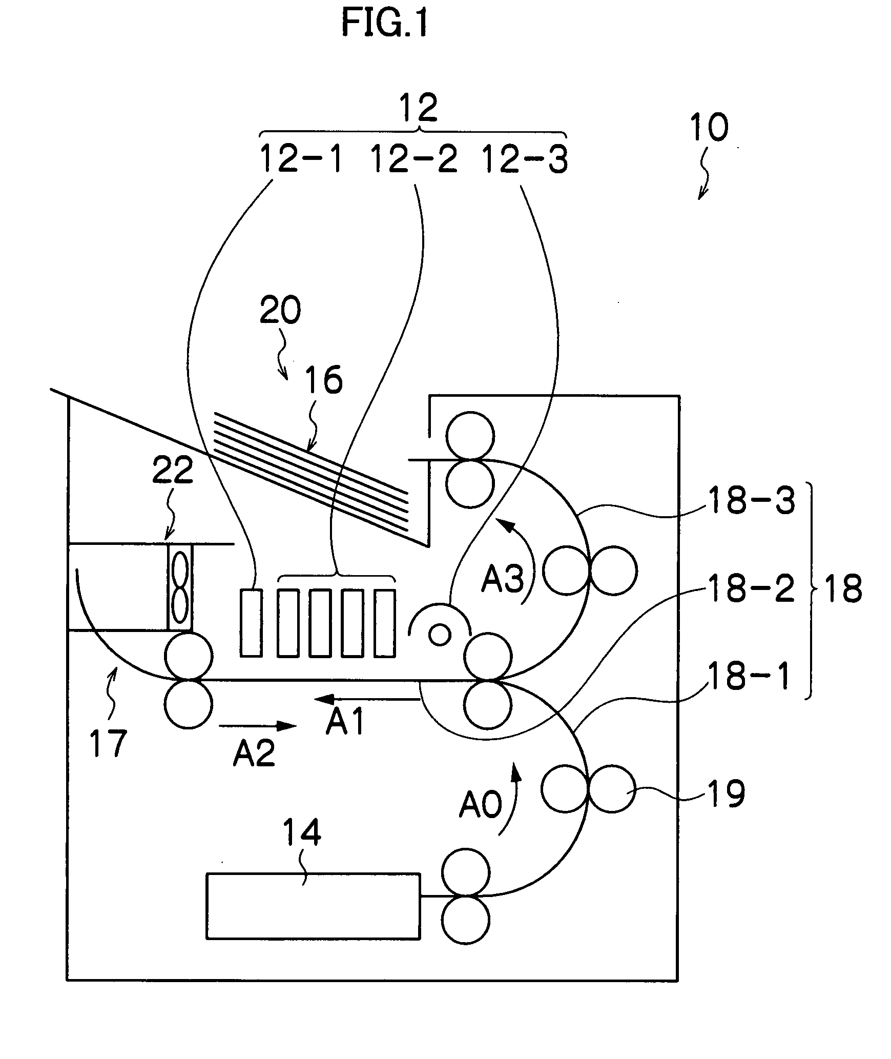
[0078]FIG. 1 is a general compositional diagram showing an approximate view of an inkjet recording apparatus serving as an image forming apparatus according to the present invention.

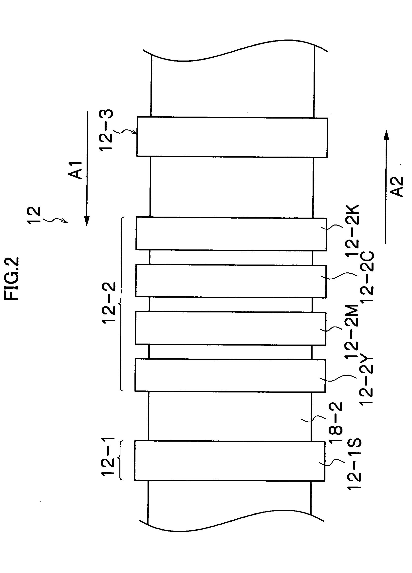
[0079]As shown in FIG. 1, the inkjet recording apparatus 10 according to the first embodiment comprises: a print unit 12 including a first liquid head group (first ejection head) 12-1 which ejects treatment liquid as a first liquid, a second liquid head group (including second ejection heads) 12-2 which ejects inks of colors as second liquids, and a UV (ultraviolet light) irradiation unit (radiation irradiation unit) 12-3; a paper supply unit 14 which supplies recording papers 16 to the print unit 12; a conveyance unit 18 which conveys the recording paper 16; and a paper output unit 20 which outputs printed recording papers 16 to the exterior.

[0080]In FIG. 1, the paper supply unit 14 is depicted as a cassette (media stacker) in which cut paper sheets are stacked and loaded, but the paper supply unit 14 i...


PUM


Abstract

The liquid ejection apparatus has: a print unit including a first ejection head which ejects a first liquid and a second ejection head which ejects a second liquid, the second ejection head being disposed on an upstream side of the first ejection head in terms of a first conveyance direction; a conveyance device which conveys a recording medium relatively with respect to the print unit; and a switch-back unit which reverses a relative conveyance direction of the recording medium, from the first conveyance direction in which the recording medium is relatively conveyed for a first time, to a second conveyance direction which is opposite to the first conveyance direction and in which the recording medium is relatively conveyed for a second time, wherein: the first ejection head ejects the first liquid toward the recording medium and the second ejection head does not eject the second liquid when the recording medium is relatively conveyed in the first conveyance direction for the first time; the switch-back unit reverses the relative conveyance direction of the recording medium from the first conveyance direction to the second conveyance direction; and the first ejection head does not eject the first liquid and the second ejection head ejects the second liquid toward the recording medium when the recording medium is relatively conveyed in the second conveyance direction for the second time.

Description

BACKGROUND OF THE INVENTION[0001]1. Field of the Invention[0002]The present invention relates to a liquid ejection method, a liquid ejection apparatus, a double-side printing method, and an image recording apparatus for double-side printing. In particular, the present invention relates to technology for preventing floating of mist and thereby preventing contamination caused by two liquids being mixed, in an inkjet apparatus which uses the two-liquid type of ink. Moreover, the present invention also relates to technology for carrying out double-side printing while it prevents contamination on a head due to floating mist occurring during ejection of liquid in an inkjet apparatus which uses a two-liquid type of ink.[0003]2. Description of the Related Art[0004]In the related art, as an image forming apparatus, an inkjet printer (inkjet recording apparatus) is known, which includes an inkjet head (liquid ejection head) having an arrangement of a plurality of nozzles (liquid ejection port...

Claims


Application Information

Patent Timeline
Patent Type & Authority Applications(United States)
IPC IPC(8): B41J29/38B41J2/01
CPCB41J2/2114B41J13/0045B41J11/002B41J3/60B41J11/00214B41J11/0022
Inventor INOUE, HIROSHIMAKUTA, TOSHIYUKI
Owner FUJIFILM CORP
Why Eureka
Try Eureka