
Stand device for motorcycle

a technology for standing devices and motorcycles, which is applied to the support devices, cycle equipment, and other supporting devices of the motorcycle, can solve the problems of limiting the layout, requiring a larger operating force, and affecting the operation of the operating element for turning the stand to the erect position, so as to reduce the play amount of the brake mechanism or maintenance, the effect of enhancing the operability of the kick starting

Inactive Publication Date: 2007-08-30
HONDA MOTOR CO LTD
View PDF2 Cites 12 Cited by
  • Summary
  • Abstract
  • Description
  • Claims
  • Application Information

AI Technical Summary

Benefits of technology

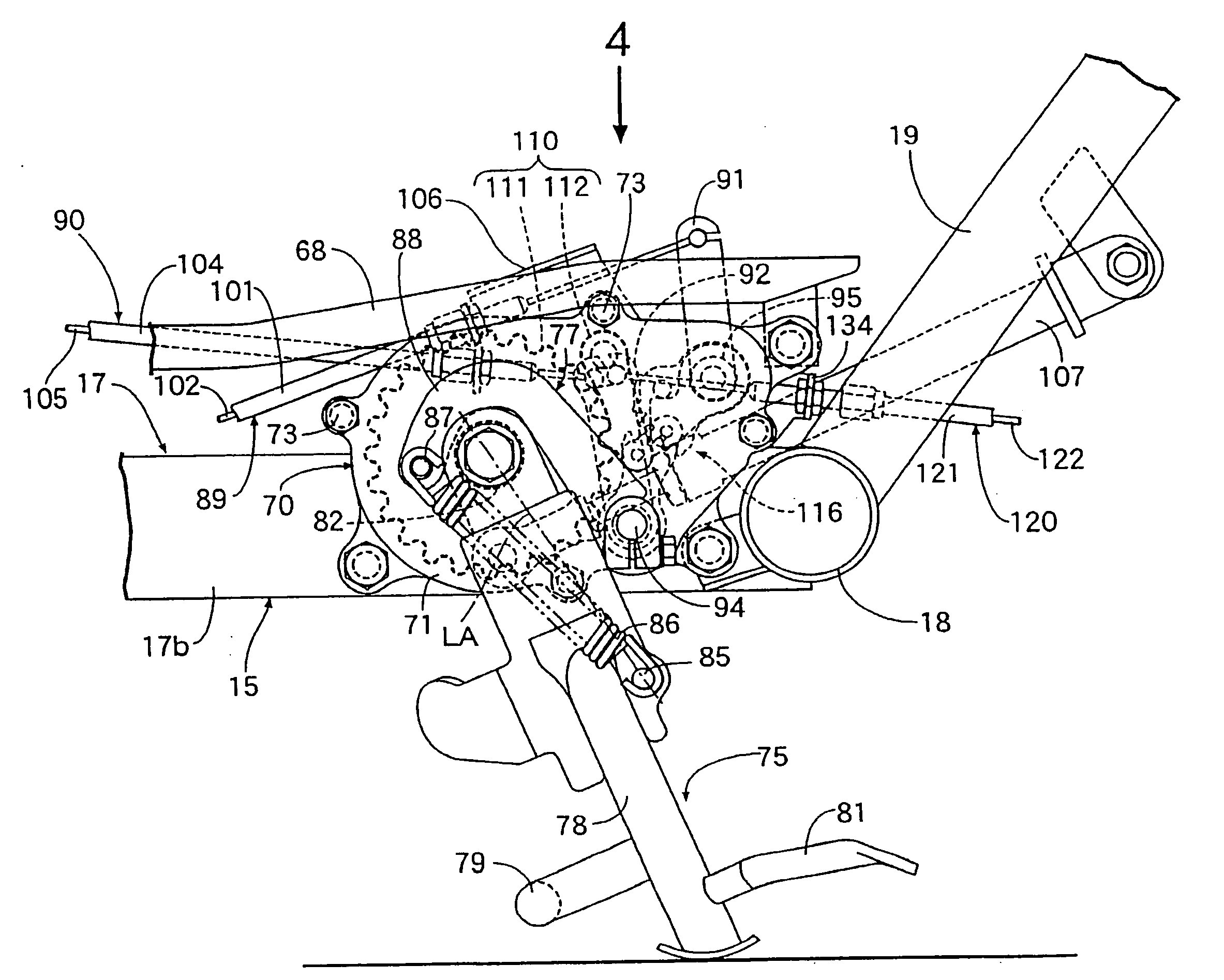
[0020]According to the first aspect of the present invention, the other end of the stand spring connected to at its one end to the stand is connected to the spring support portion of the spring support member, the spring support member is interlocked and connected to the operating element so as to permit the position of the spring support portion to be changed according to a manual operation of the operating element, and, at the position of the spring support portion determined to an operation of the operating element to the erect position side, the stand spring is in the state of urging the stand toward the erect position side. Therefore, the stand can be turned from the stored position to the erect position by utilizing the spring force of the stand spring, and only a small operating force is needed for operating the spring support member so as to change the position of the spring support portion. As a result, it is possible to turn the stand to the erect position side while suppressing the operating load to a low level.
[0046]According to the third aspect of the present invention, the kick-start disabling mechanism has the simple structure in which the engaging member is only engaged with the connecting member of the kick-starter, so that a compact configuration can be realized.

Problems solved by technology

Therefore, the operating load on the operating element for turning the stand to the erect position is necessarily large.
In this case, however, a larger operating force is necessary if the wire is connected to a position close to a turning shaft of the stand.
However, there is a limitation on the layout, and it is difficult to design the preferred configuration.
On the other hand, when the pawl is reduced in size, a lowering in strength may be brought about.
In order to increase the strength, it is necessary to use a high-strength material or to subject a material to a hardening treatment, leading to an increase in cost.
Sho 59-21828, an error would be generated between an erecting operation of the stand and a brake operation due to a decrease in a play amount in the brake mechanism or the thickness of a brake pad, resulting in that the operabilities of these operations may be mutually influenced.

Method used


Image

  • Stand device for motorcycle
  • Stand device for motorcycle
  • Stand device for motorcycle

Examples


first embodiment

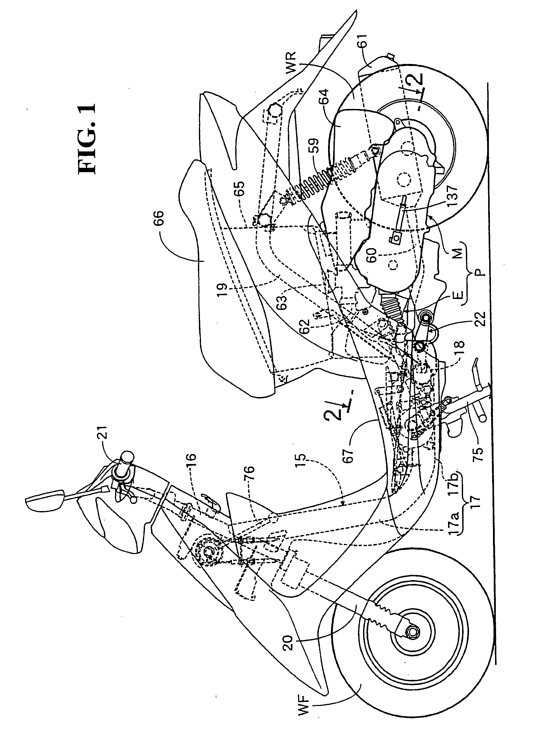
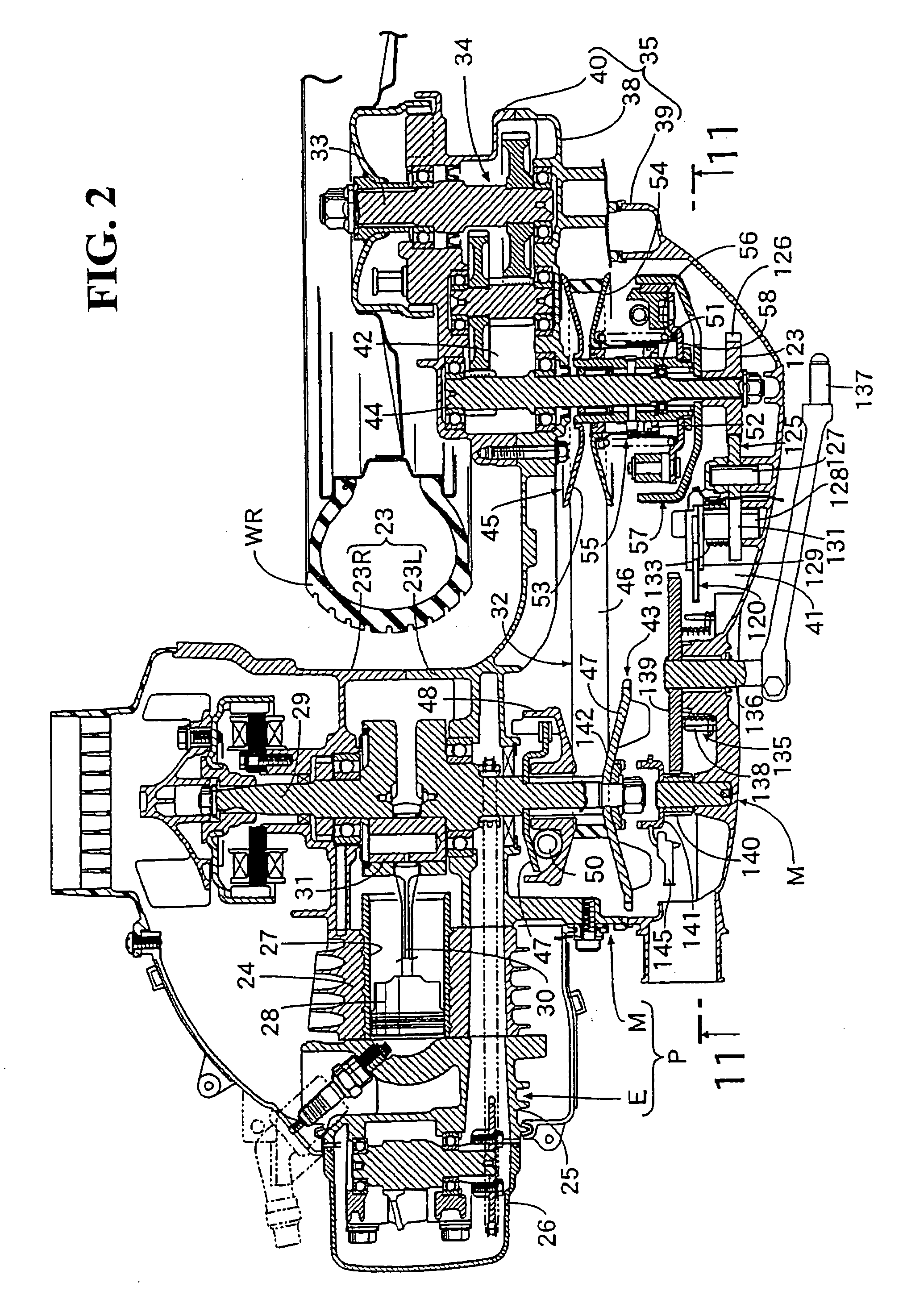
[0065]FIGS. 1 to 11 show the present invention. First, in FIG. 1, a vehicle body frame 15 of the motor scooter type motorcycle includes a main frame pipe 17 with a head pipe 16 attached to the front end thereof. A cross pipe 18 is rectangularly attached to the rear end of the main frame pipe 17. A left-right pair of rear frame pipes 19 are connected at their front ends, respectively, to both end portions of the cross pipe 18.

[0066]The main frame pipe 17 integrally has a down frame portion 17a inclined rearwardly downwards from the head pipe 16. A lower frame portion 17b extends substantially horizontally rearwards from the rear end of the down frame portion 17a. The cross pipe 18 extends in the left-right direction of the vehicle body frame 15. A central portion in the axial direction of the cross pipe 18 is rectangularly attached to a rear end portion of the main frame pipe 17.

[0067]A front fork 20 formed astride a front wheel WF is steerably borne on the head pipe 16. A steering h...

second embodiment

[0130] as just-mentioned, the stand 75 is urged by the auxiliary coil spring 150 in addition to the stand spring 86, whereby the operating load can be reduced while securing a sufficient urging force for turning the stand 75.

[0131]FIG. 14 shows a third embodiment of the present invention, in which the operating lever 76 is attached to a turning connecting member 151 turnably borne on the vehicle body frame 15 (refer to the first embodiment) through a support shaft 154, the inner cable 102 of the storing operating force transmitting mechanism 89 is connected to a first connecting arm 152 possessed by the turning connecting member 151, and the inner cable 105 of the erecting operating force transmitting mechanism 90 is connected to a second connecting arm 153 possessed by the turning connecting member 151.

third embodiment

[0132] also, by an operation of turning the operating lever 76, an operating force from the operating lever 76 can be transmitted to the storing operating force transmitting mechanism 89 and the erecting operating force transmitting mechanism 90.

[0133]While some embodiments of the present invention have been described above, the present invention is not limited to the above embodiments, and various design modifications can be made within the scope of the present invention as set forth in the claims.

[0134]For example, the present invention is applicable also to two-wheeled vehicles other than the motor scooter type motorcycle shown in the drawings and to bicycles.


PUM


Abstract

A stand device for a motorcycle includes an interlocking mechanism having a coil-formed stand spring connected to a stand at one end thereof. A spring support member has a spring support portion connected with the other end of the stand spring and is interlocked and connected to an operating element so that the position of the spring support portion can be changed according to a manual operation of an operating element. The position of the spring support portion determined according to the operation of the operating element toward the erect position side is so set that the stand spring is put in the state of urging the stand toward the erect position side.

Description

CROSS-REFERENCE TO RELATED APPLICATIONS[0001]This nonprovisional application claims priority under 35 U.S.C. § 119(a) on Patent Application Nos. 2006-053674, 2006-053675 and 2006-053676, each filed in Japan on Feb. 28, 2006. The entirety of each of these documents is incorporated herein by reference.FIELD OF THE INVENTION[0002]A first aspect of the present invention relates to a stand device for a motorcycle, including an operating element capable of being manually operated, a stand turnable between an erect position for obtaining a parking condition and a stored position for canceling the parking condition, and an interlocking mechanism by which the stand is turned from the stored position to the erect position according to a manual operation of the operating element.[0003]A second aspect of the present invention relates to a stand device for a motorcycle in which a stand shaft attached to a stand is borne on a vehicle body frame or a support body fixed to the vehicle body frame, i...

Claims


Application Information

Patent Timeline
Patent Type & Authority Applications(United States)
IPC IPC(8): B62H7/00
CPCB62H1/02B62H1/04
Inventor OGAWA, MASAOAKIBA, MASAHIRO
Owner HONDA MOTOR CO LTD
Learn More