Tank unit, ink jet recording head and method of manufacturing tank unit and ink jet recording head
a technology of tank unit, which is applied in the field of tank unit can solve the problems of difficult to exert washing water washing pressure, ink discharge defect, and ink jet recording head reliability decline, and achieve the effect of simple and attained, low cost, and simple and attained
- Summary
- Abstract
- Description
- Claims
- Application Information
AI Technical Summary
Benefits of technology
Problems solved by technology
Method used
Image
Examples
first embodiment
of the Present Invention
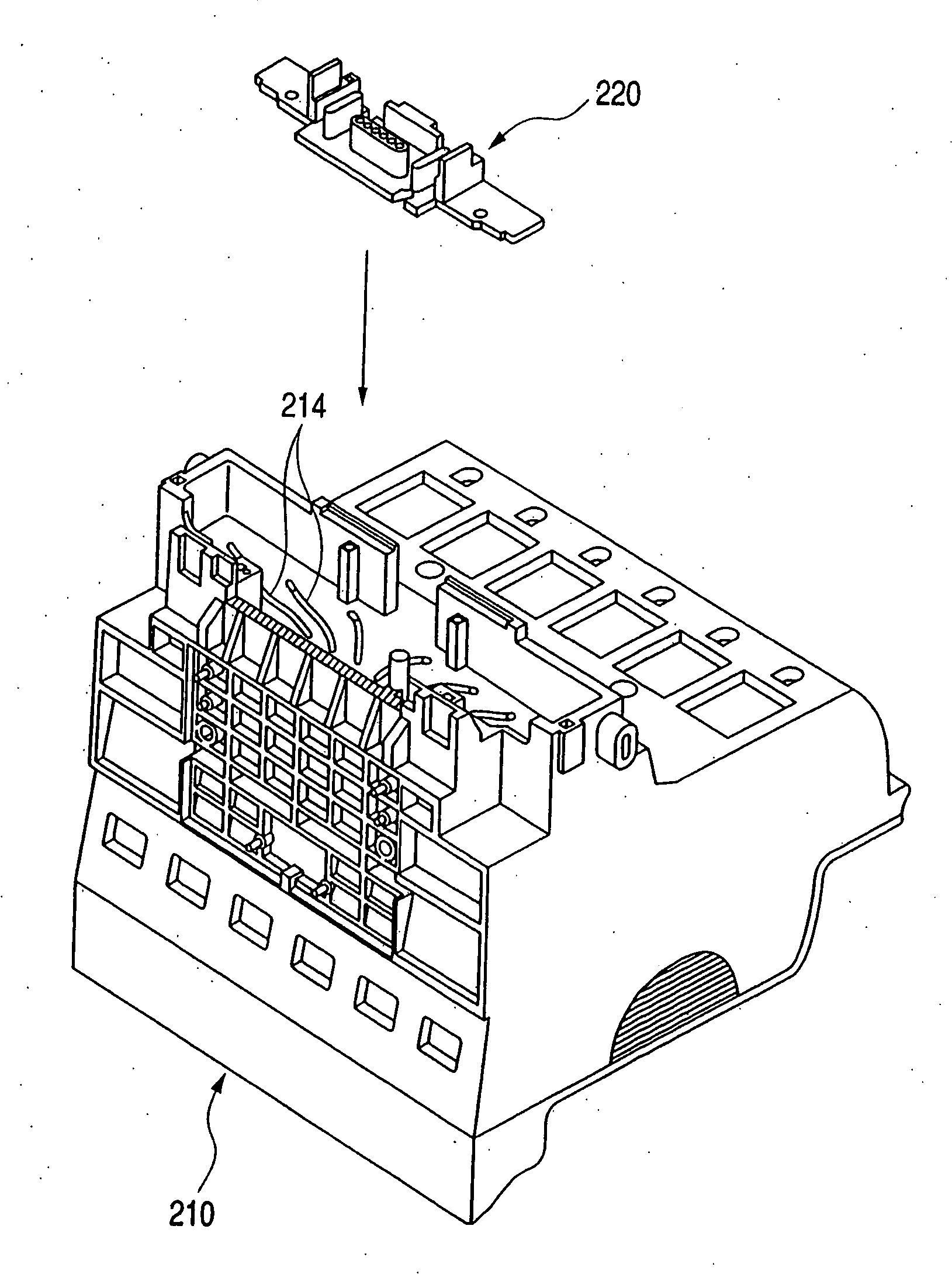
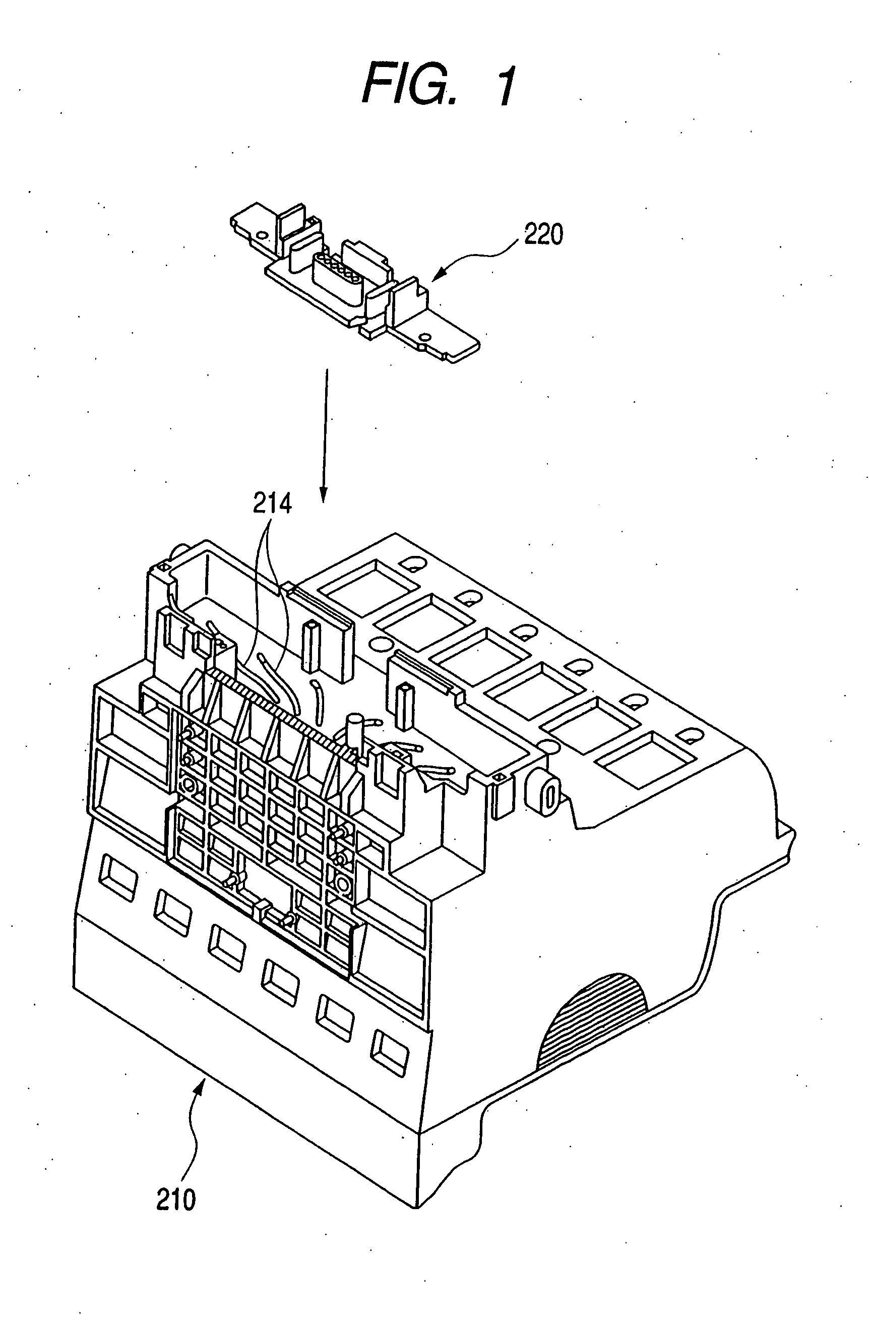
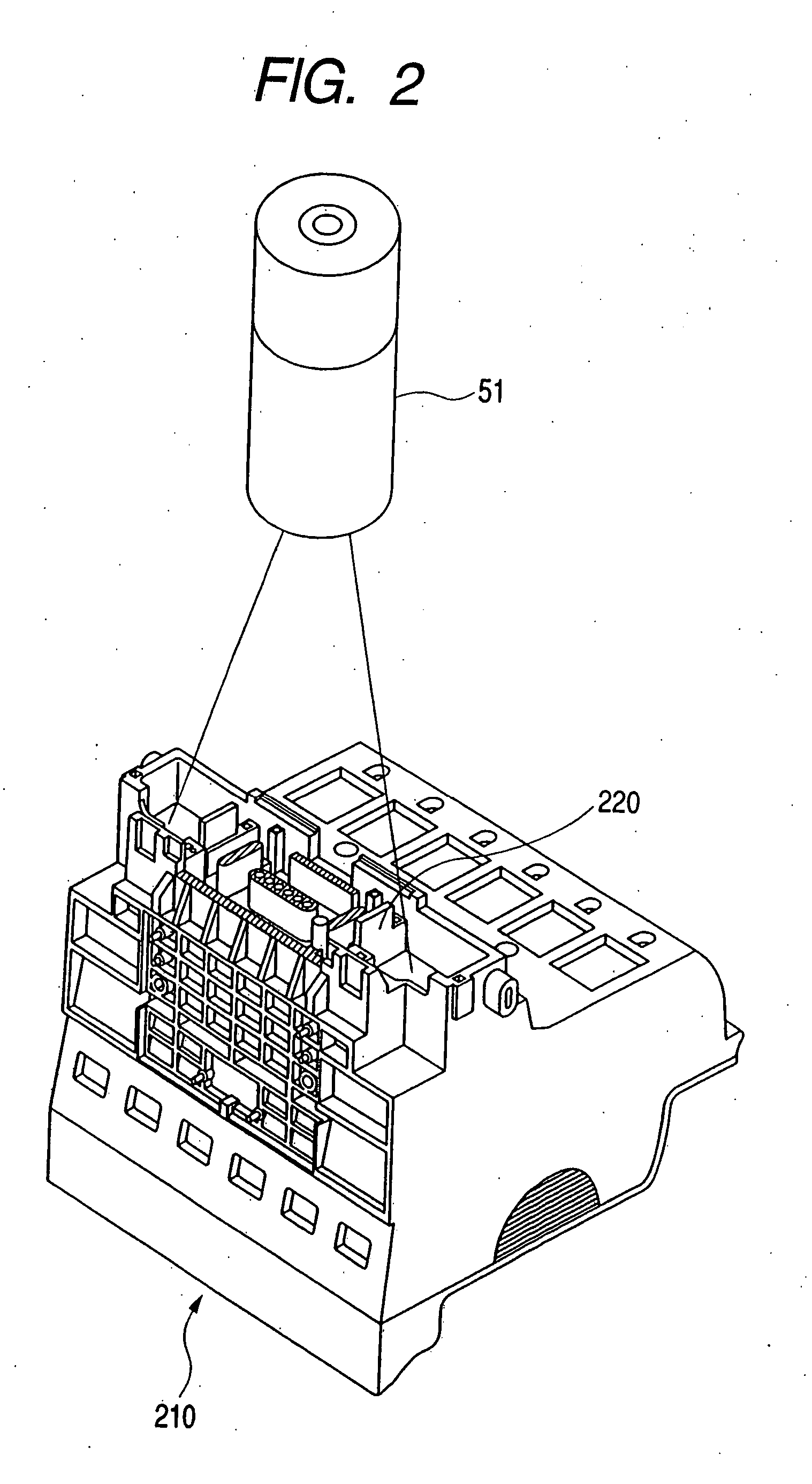
[0061] Next, the construction and features of the ink jet recording head according to a first embodiment of the present invention, will be described with reference to FIGS. 1 through 4C. In the thus-constructed ink jet recording head 20 in the first embodiment of the present invention the tank holder 210 itself is molded of a resin containing a dye stuff or a pigment that absorbs the laser beams in order to dispose a non-transmissive material that does not transmit the laser beams in a junction surface area between the flow path forming member 220 for forming the ink flow path 224 and the tank holder 210. On the other hand, the flow path forming member 220 is molded of a resin that transmits the laser beams, and only a junction surface 223 of the flow path forming member 220 is a protruded portion taking a protruded shape unlike other non-junction surfaces. Further, all the junction surfaces formed on the tank holder 210 and in the periphery of the portion fo...
second embodiment
of the Present Invention
[0070] Next, a construction and features of the ink jet recording head according to a second embodiment of the present invention will be explained with reference to FIGS. 11A, 11B and 1C. FIGS. 11A, 11B and 11C are schematic side surface partial sectional views showing a step of connecting the flow path forming member to the tank holder of the ink jet recording head in the second embodiment of the present invention. FIG. 11A shows a relative relationship between the tank holder and the flow path forming member before the connection. FIG. 11B shows a state in which the flow path forming member is irradiated with the laser beam in a way that abuts the flow path forming member on the tank holder. FIG. 11C shows a connected state. The same members as those in the first embodiment are marked with the same reference numerals.
[0071] In FIGS. 11A to 11C, the materials composing the flow path forming member 220 and the tank holder 211 are the same as those in the fir...
third embodiment
of the Present Invention
[0075] Next, a construction and features of the ink jet recording head according to a third embodiment of the present invention will be explained with reference to FIGS. 12A, 12B and 12C. FIGS. 12A, 12B and 12C are schematic side surface partial sectional views showing a step of connecting the flow path forming member to the tank holder of the ink jet recording head in the third embodiment of the present invention. FIG. 12A shows a relative relationship between the tank holder and the flow path forming member before the connection. FIG. 12B shows a state in which the flow path forming member is irradiated with the laser beam in a way that abuts the flow path forming member on the tank holder. FIG. 12C shows a connected state. The same members as those in the first embodiment are marked with the same reference numerals.
[0076] In FIG. 12, the materials composing a flow path forming member 221 and a tank holder 212 are the same as those in the first embodiment....
PUM
 Abstract
Description
Claims
Application Information
 - R&D
- Intellectual Property
- Life Sciences
- Materials
- Tech Scout
- Unparalleled Data Quality
- Higher Quality Content
- 60% Fewer Hallucinations
Browse by: Latest US Patents, China's latest patents, Technical Efficacy Thesaurus, Application Domain, Technology Topic, Popular Technical Reports.
© 2025 PatSnap. All rights reserved.Legal|Privacy policy|Modern Slavery Act Transparency Statement|Sitemap|About US| Contact US: help@patsnap.com


