
Vehicular flasher unit operative to provide a heartbeat flasher scheme

a technology of heartbeat flasher and flasher scheme, which is applied in the direction of instruments, signalling systems, transportation and packaging, etc., can solve the problems of inflexible flasher unit types in many ways

Inactive Publication Date: 2007-08-23
XTREME ENGINEERED SOLUTIONS
View PDF27 Cites 39 Cited by
  • Summary
  • Abstract
  • Description
  • Claims
  • Application Information

AI Technical Summary

Benefits of technology

The solution provides increased safety through enhanced turn signal and emergency hazard visibility, reduces wiring complexity and cost, and allows for customizable flash patterns, effectively addressing the limitations of existing flasher units.

Problems solved by technology

These types of flasher units are inflexible in many ways.

Method used


Image

  • Vehicular flasher unit operative to provide a heartbeat flasher scheme
  • Vehicular flasher unit operative to provide a heartbeat flasher scheme
  • Vehicular flasher unit operative to provide a heartbeat flasher scheme

Examples


Embodiment Construction

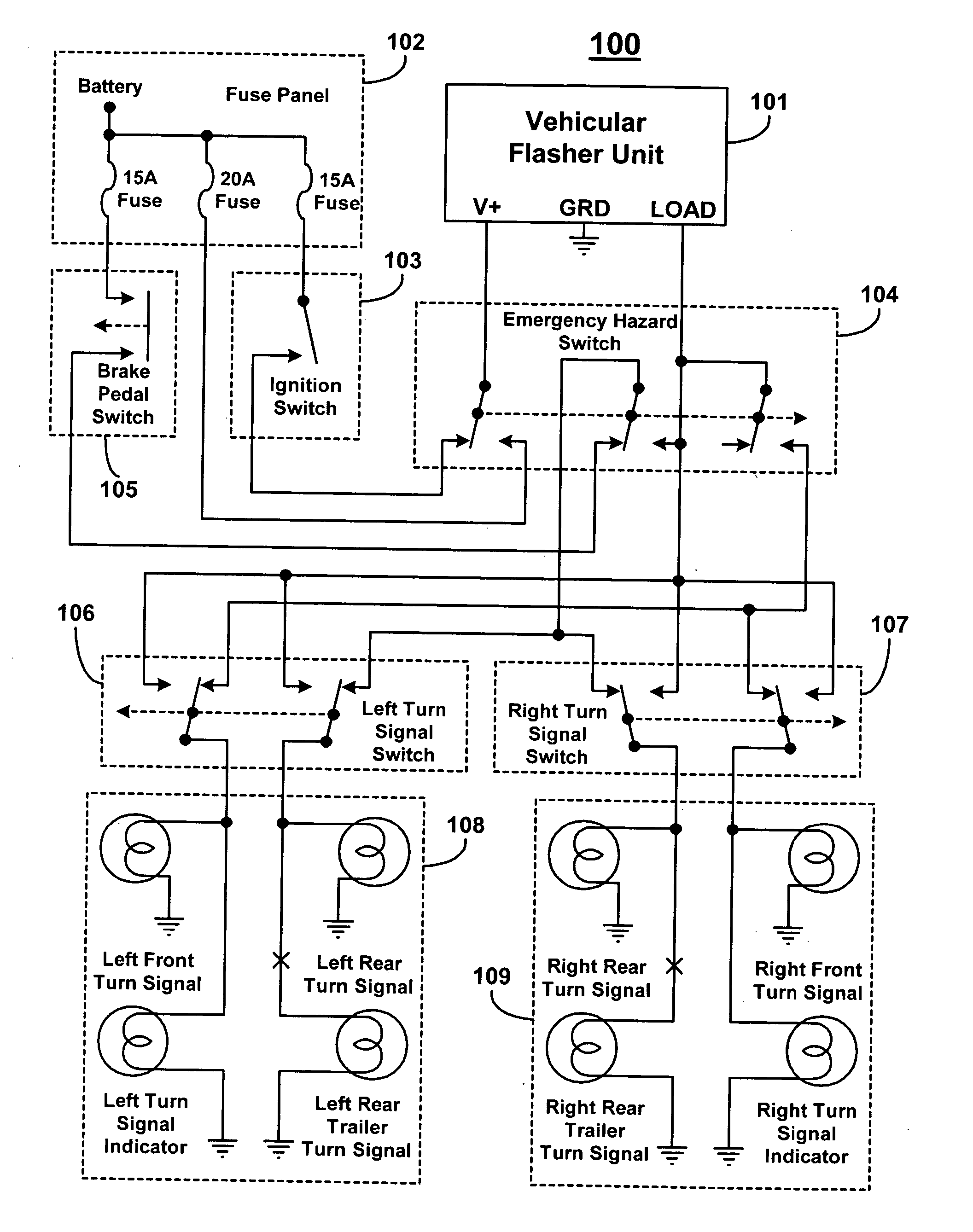
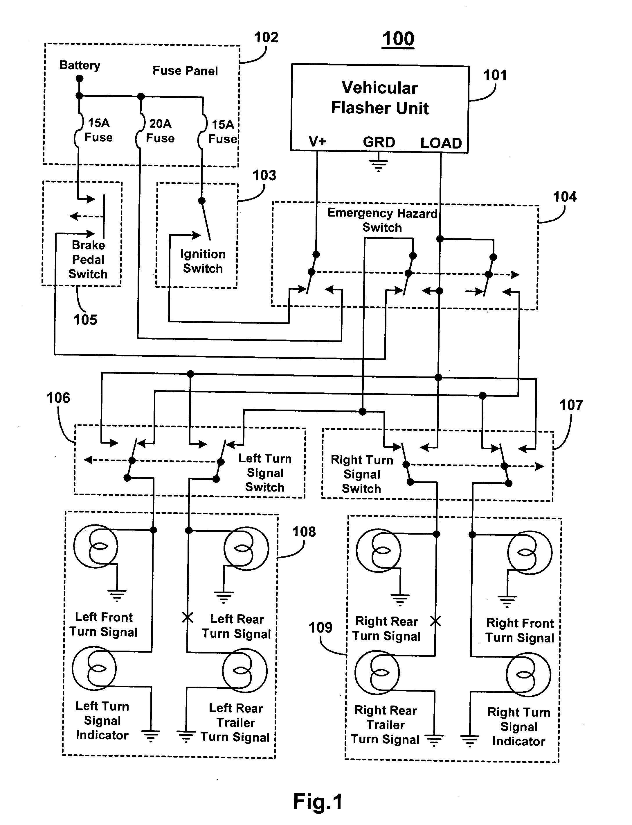
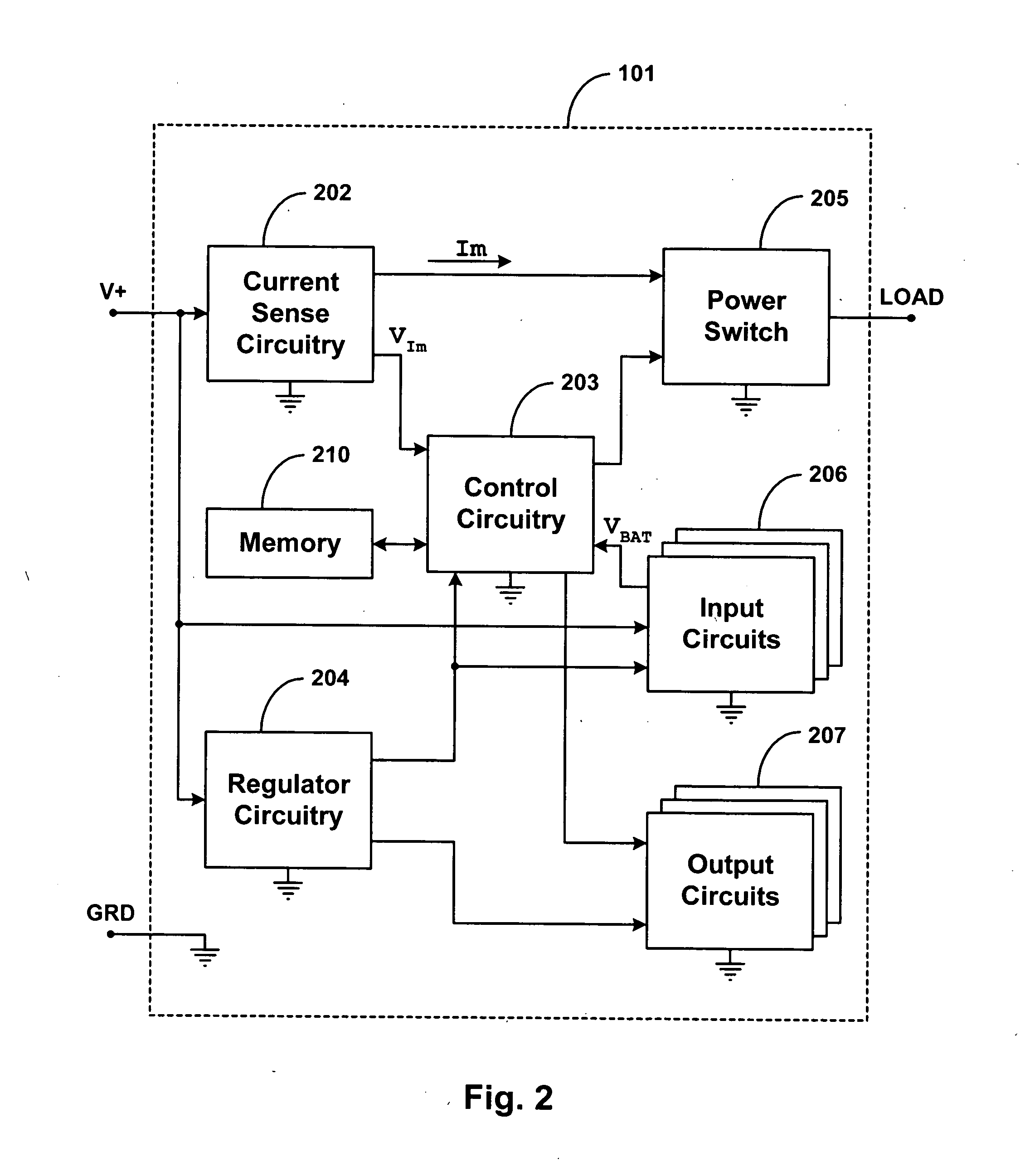
[0020] The present application relates to a vehicular flasher unit having user selectable flasher schemes stored in memory which illuminate vehicle flasher lights using pulse width modulated (PWM) signals. In one particular example, the vehicular flasher unit has control circuitry; memory which is accessible by the control circuitry and has a plurality of PWM flasher scheme data sets stored therein which correspond to a plurality of flasher schemes for a vehicle flasher light; a flasher scheme selection input to the control circuitry; a flasher enable input to the control circuits which enables a flasher scheme in the vehicular flasher light; and a light illumination output from the control circuitry which controls illumination of the vehicle flasher light. Flasher enable signals at the flasher enable input may be driven by a current sense circuit for detecting different lamp load currents which correspond to different switch actuations and / or status conditions (e.g. actuation of le...


PUM


Abstract

In one illustrative example, a vehicular flasher unit is operative to provide a heartbeat flasher scheme in vehicle flasher lights. One illustrative technique in the vehicular flasher unit involves monitoring a flasher enable input to identify a flasher enable signal and producing, at a light illumination output in response to identifying the flasher enable signal, a heartbeat flashing scheme in the vehicle flasher lights. The heartbeat flashing scheme has a repeating sequence of two heartbeat pulse flashes in the vehicle flasher lights which include a first heartbeat pulse flash and a second heartbeat flash. Each first heartbeat pulse flash has a first peak intensity in the vehicle flasher lights and each second heartbeat pulse flash has a second peak intensity in the vehicle flasher lights that is preferably different from the first peak intensity. Further, each first heartbeat pulse flash is separated from its following second heartbeat pulse flash by a first duration, and each second heartbeat pulse flash is separated from its following first heartbeat pulse by a second duration that is greater than the first.

Description

CROSS-REFERENCE TO RELATED APPLICATION [0001] This patent application is a continuation of and claims priority to U.S. patent application having Ser. No. 11 / 250,736, filing date of Oct. 14, 2005, and title of “Vehicular Flasher Unit Having Selectable Flasher Schemes Illuminated With Pules Width Modulated Signals,” now U.S. Pat. No. 7,199,704, which further claims priority to U.S. provisional patent application having Ser. No. 60 / 619,441 entitled “Programmable Automotive Turn signal Flasher (PATSF)” having a filing date of 15 Oct. 2004, which is are hereby incorporated by reference herein.BACKGROUND [0002] 1. Field of the Technology [0003] The present application relates generally to vehicular flasher units for illuminating vehicle flasher lights (e.g. turn signal flashers) for vehicles (e.g. automobiles), and more particularly to vehicular flasher units having selectable flasher schemes which utilize pulse width modulated (PWM) signals to illuminate the vehicle flasher lights, where...

Claims


Application Information

Patent Timeline
Patent Type & Authority Applications(United States)
IPC IPC(8): B60Q1/52
CPCB60Q1/34B60Q1/38H05B39/09G08B5/38B60Q1/46B60Q1/381
Inventor HERRIG, HANZHOLLE, DEAN
Owner XTREME ENGINEERED SOLUTIONS
Learn More